DeskPi Super6C (DP-0008)
- Overview
- Hardware
- Flash & Boot
- Cluster & FAQ
Description
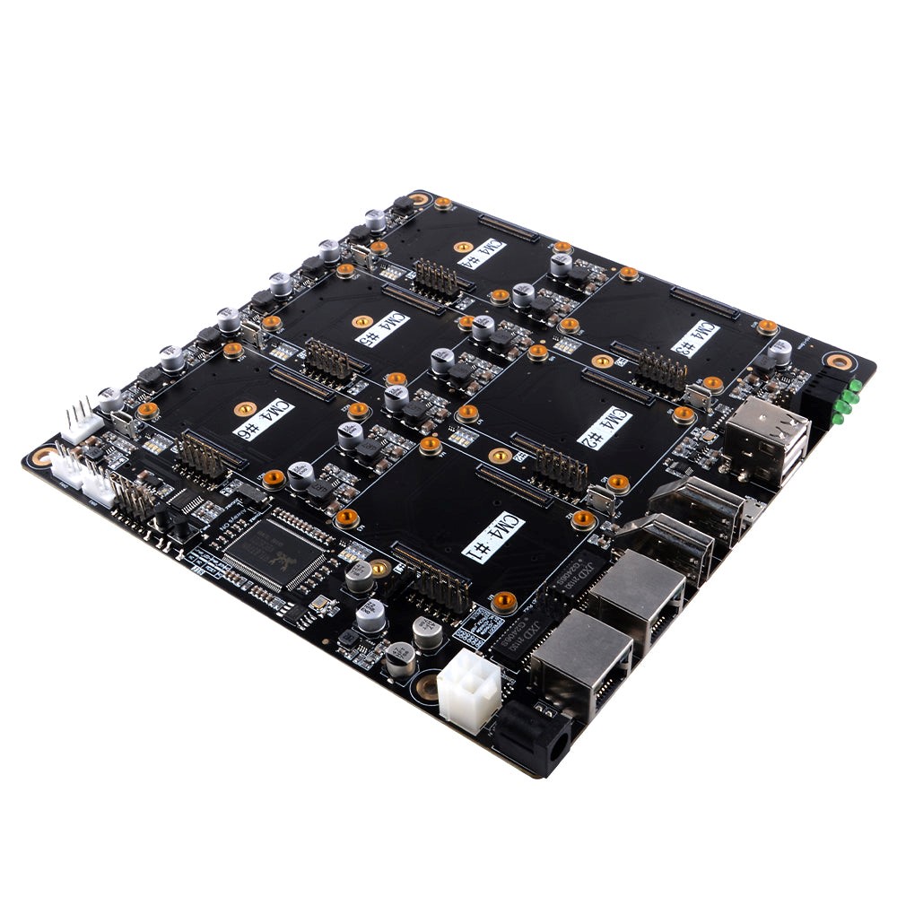
DeskPi Super6C is a Raspberry Pi cluster board in a standard Mini-ITX form factor, supporting up to 6 Raspberry Pi CM4 Compute Modules.
Per CM4 node: M.2 2280 slot (PCIe Gen 2 x1); TF Card slot; 5V FAN Header; Micro USB 2.0
1st CM4 node only: USB Host A 2.0 × 2; USB Host 2.54 4-pins × 2; HDMI 2.0 × 1; HDMI 1.4a × 1
Applications
- Self-hosted: Host cloud applications locally or at the edge
- Learning: Kubernetes, Docker, Serverless
- Development: Build cloud-native CI/CD for ARM edge infrastructure
- Storage: 6× ARM NAS node or Ceph node
Compatibility
Raspberry Pi CM5 does not support Super6C. Use Super4C for CM5 workloads.
BPi-CM4 V1.0 test results:
| Interface | Compatibility |
|---|---|
| USB Port 1 | YES |
| USB Port 2 | YES |
| HDMI1 | YES |
| HDMI2 | NO |
| ETH1 | NO |
| ETH2 | NO |
| Front USB Ports | NO |
| M.2 NVMe SSD | NO |
OPi-CM4 V1.4 and OPi-CM5 V1.1: all interfaces NO (CM5 cannot boot at all).
Key Features
- Standard Mini-ITX Form Factor: Fits standard Mini-ITX PC cases and 10-inch / 19-inch rack enclosures.
- 6-Node High Compute Density: Houses up to 6× Raspberry Pi CM4 modules with independent power management.
- Dedicated NVMe Storage: Dedicated M.2 2280 PCIe Gen 2 x1 NVMe SSD slot per node (up to 6× SSDs).
- Integrated Gigabit Switch: Onboard RTL8370MB 8-port Gigabit Ethernet switch interconnecting all nodes and dual RJ45 uplinks.
- Rich I/O Connectivity on Node 1: Dual full-size HDMI, dual USB 2.0 host ports, and Micro-USB eMMC flashing port.
- Advanced Thermal Management: Three 4-pin PWM fan headers for targeted cross-flow chassis cooling.
Software

Port Definitions
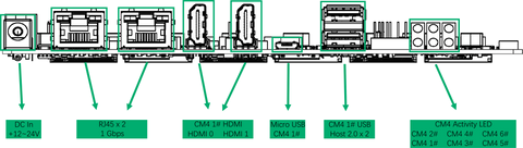
- 1× DC IN +12~24V
- 2× RJ45 Gigabit Ethernet Port (1Gbps)
- 2× Full-Sized HDMI Ports
- 1× Micro USB Port from CM4 1# (Flashing eMMC)
- 2× CM4 1# USB Host 2.0
- 6× CM4 Activity LED
- 3× Fan Pin Header
- 1× Always ON switch
Power Supply Specifications
Recommended: FJ-SW2025G1904730 — INPUT: 100-240V~50/60Hz 2.0A Max; OUTPUT: 19.0V approximately 4.73A, 89.87W

Pay close attention to startup order — incorrect order may cause sparks at the DC port!
- Insert the DC adapter into the Super6C DC interface first.
- Then insert the power plug into the wall socket.
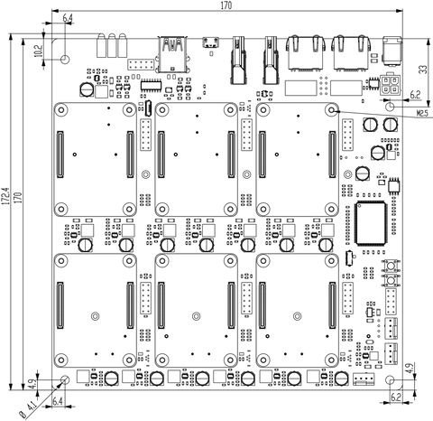
Mechanical Drawing

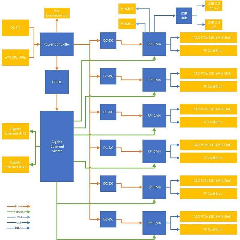
Block Scheme
Pin Headers Definitions
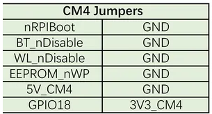
CM4 Jumpers Functions
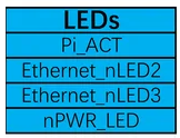
LED Definitions
4-Pin ATX Power Pins
- 12V Pin & GND:
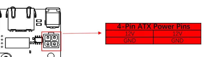
12V power input pinout
- Power & Reset Control:
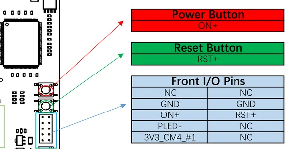
Front panel power and reset switch headers
- Pin Header Distribution:
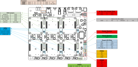
Full ATX pin header distribution
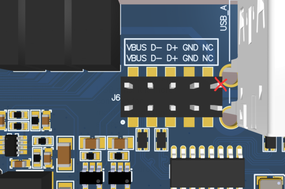
- J6: For 9-pin USB (i845D/i845E/SiS 650 chipsets), drop the pins. For 10-pin (i815/KT133), the pin can be reserved — check your motherboard manual:
- J27: Internal production use only. DO NOT CONNECT.
- J11/J13: PoE1/PoE2 — not available. DO NOT CONNECT.
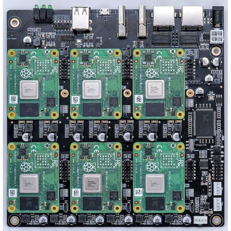
Installing CM4 Module
Align the CM4 with the two connectors on the board and press firmly until it snaps into place.
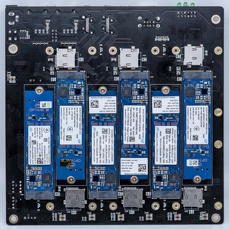
Install SSD if needed:
Flash Image to eMMC
Prerequisites:
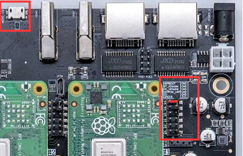
- Fit the
nRPBOOTjumper onJ2(disables eMMC Boot). - Connect a Micro USB cable from the
MCRO_USBslave port to your host. - Do not power up yet.
Windows
Download and run: rpiboot Windows Installer
- Plug host USB into the USB SLAVE port, then apply power.
- Windows installs the driver automatically.
- Run
RPiBoot.exe— eMMC appears as a USB mass storage device. - Use Raspberry Pi Imager to flash your OS.
- Remove
J2jumper and power cycle.
Linux / macOS
sudo apt install git libusb-1.0-0-dev
git clone --depth=1 https://github.com/raspberrypi/usbboot
cd usbboot
make
sudo ./rpiboot
Plug host into Super6C USB slave port and power on. After rpiboot completes:
sudo dd if=your_os_image.img of=/dev/sdX bs=4MiB
Remove J2 jumper and power cycle.
CM4 Bootloader
The default bootloader may be outdated. Configure BOOT_ORDER in boot.conf:
- Network boot:
BOOT_ORDER=0xf2 - SD/eMMC boot:
BOOT_ORDER=0xf1 - USB with eMMC fallback:
BOOT_ORDER=0xf15
cd usbboot/recovery
# Edit boot.conf, then:
./update-pieeprom.sh
../rpiboot -d .
Flash bootloader EEPROM (ensure EEPROM_nWP is NOT pulled low):
# Writes recovery/pieeprom.bin to the bootloader EEPROM.
./rpiboot -d recovery
Troubleshooting
For FAT32 partition issues (some CM3 modules):
sudo parted /dev/sdX
(parted) mkpart primary fat32 4MiB 64MiB
(parted) q
sudo mkfs.vfat -F32 /dev/sdX
CM4 Lite (no eMMC): Flash OS to TF card or SSD and insert into the slot.
Build a Cluster with Ansible
These steps use Raspberry Pi OS 2021-11-08. The latest OS may not need the dtoverlay=dwc2 config.
Initial Setup
- Download Raspberry Pi OS 64-bit image and flash to TF card.
- Add to
/boot/config.txt:
dtoverlay=dwc2,dr_mode=host
- Create an empty
sshfile in/boot. - Insert TF card; connect power, HDMI, keyboard, and Ethernet to ETH1.
- Press
PWR_BTNto boot.
Default credentials: pi / raspberry
Install Ansible
sudo apt remove ansible
sudo apt purge -y python2.7-minimal
sudo apt update && sudo apt upgrade -y

# Build Python 3.8
sudo apt-get install -y build-essential tk-dev libncurses5-dev \
  libncursesw5-dev libreadline6-dev libdb5.3-dev libgdbm-dev libsqlite3-dev \
  libssl-dev libbz2-dev libexpat1-dev liblzma-dev zlib1g-dev libffi-dev

version=3.8.5
wget https://www.python.org/ftp/python/$version/Python-$version.tgz
tar zxf Python-$version.tgz && cd Python-$version
./configure --enable-optimizations
make -j4 && sudo make altinstall

pip3 install ansible --user
Add ~/.local/bin to PATH, then set up your Ansible project:
mkdir Ansible
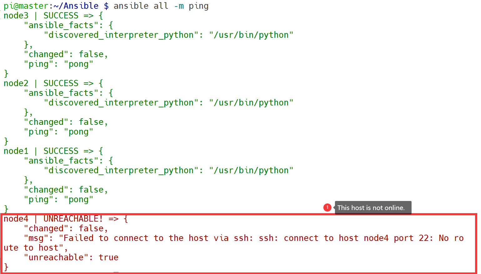
Configure hosts inventory and test:
ansible all -m ping
FAQ
Q: Can Super6C support CM5? A: Only partially. Use Super4C for CM5 workloads.
Q: What workloads can I run? A: Kubernetes/K3S, Docker, Serverless, distributed ML, NAS (Nextcloud, Minio, Seafile), Minecraft, Plex, databases.
Q: Which Raspberry Pi models are compatible? A: All CM4 variants (with and without eMMC).
Q: Are compute modules included? A: No — only the cluster motherboard and 100W power adapter.
Q: Where can Super6C boot from? A: eMMC, SD Card, or network boot.
Q: Does each node get its own IP address? A: Yes.
Q: How do nodes communicate? A: Via the onboard 8-port 1 Gbps switch. Two external RJ45 ports connect to your upstream network.
Q: Do all 6 slots need to be filled? A: No — the cluster runs with any number of nodes. Add more when needed.
Q: Can I flash modules through the board? A: Yes, via the Micro USB slave port.
Q: Does it work with ATX 12V? A: Yes.
Recommended Ecosystem & Enclosures
To turn the Super6C bare motherboard into a finished desktop server or rackmount appliance:
| Component | Recommended Solution | Documentation |
|---|---|---|
| Desktop ITX Chassis | DeskPi ITX Case Kit (DP-0010) | Custom acrylic & aluminum Mini-ITX enclosure with front power controls |
| 10" Rackmount Tray | 10-inch Mini-PC Tray (DP-0073) | Mounts standard Mini-ITX form-factor motherboards into 10" RackMate racks |
| Next-Gen CM5 Cluster | DeskPi Super4C (DP-0040) | 4-node native Raspberry Pi Compute Module 5 cluster board |
| All SBC Comparisons | Hardware Compatibility Matrix | Comprehensive multi-node and single-board compatibility table |