DeskPi ITX Case Kit for Super6C (DP-0010)
Description
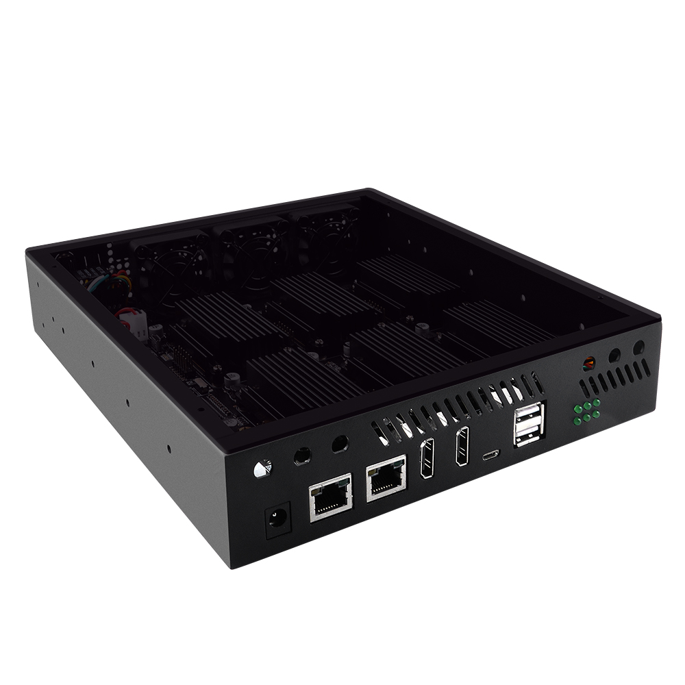
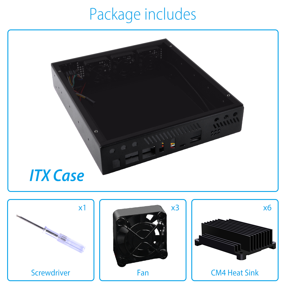
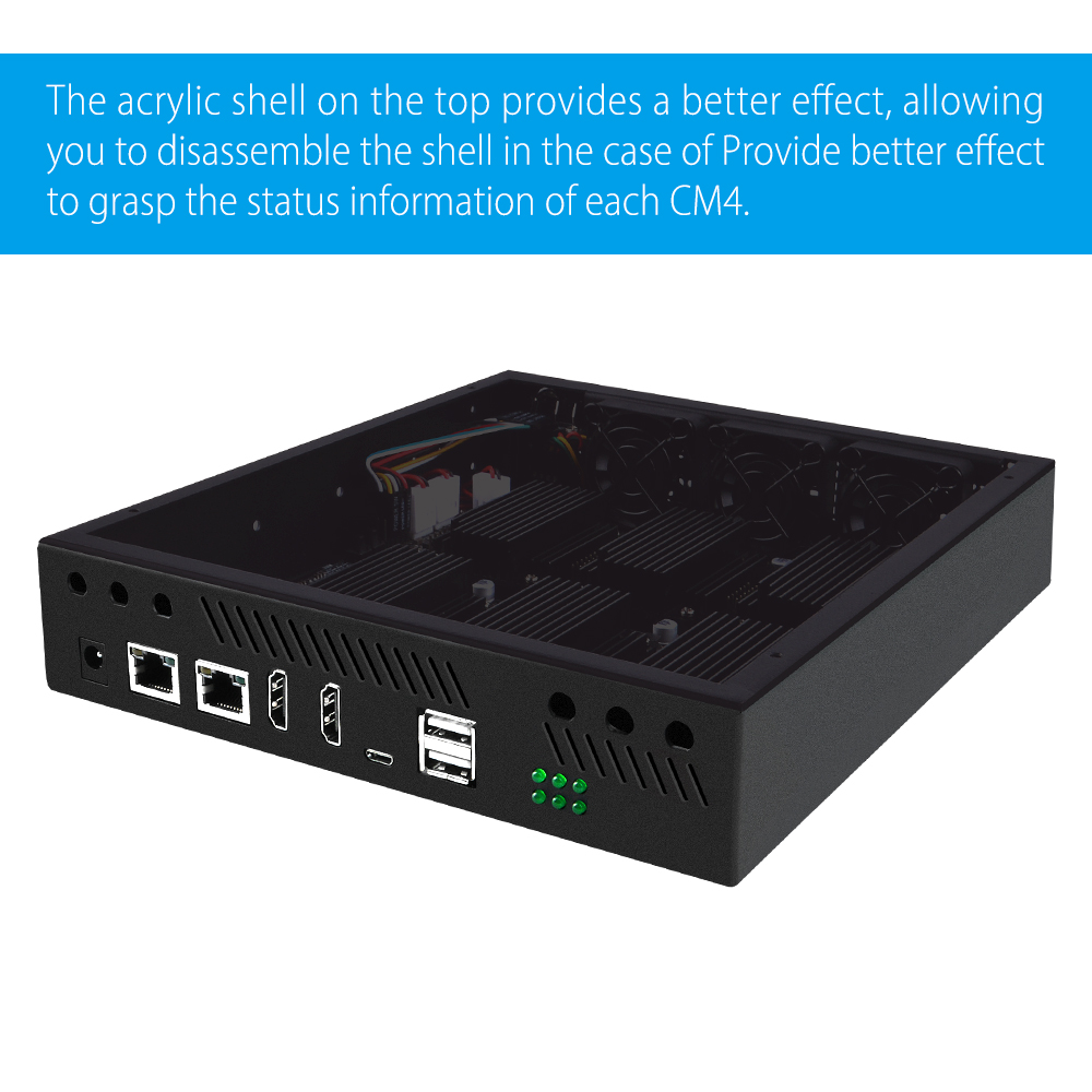
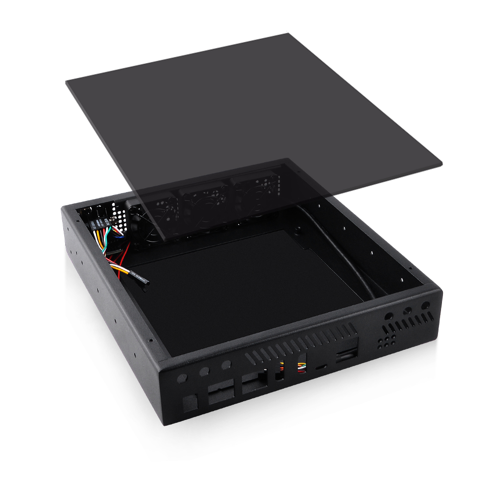
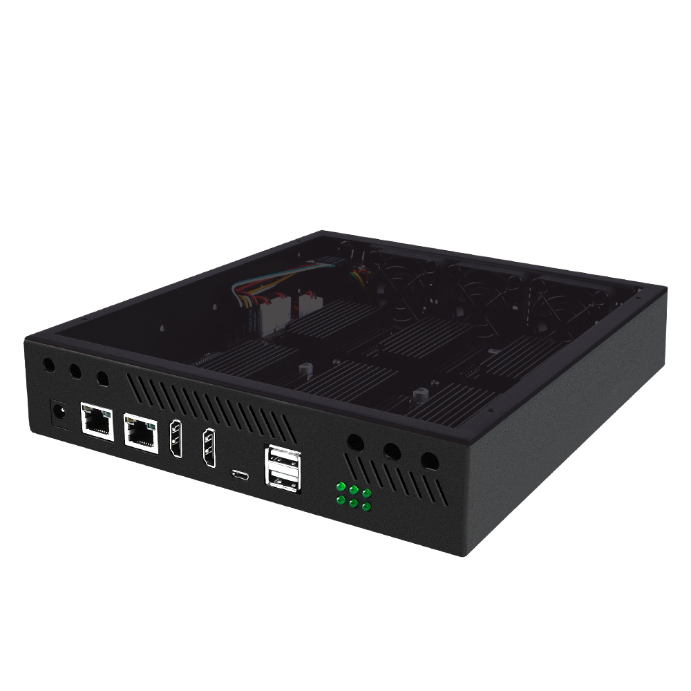
The DeskPi ITX Case Kit is a custom Mini-ITX chassis engineered exclusively for the DeskPi Super6C 6-Node Cluster Board. Built with a rigid metal base and a transparent acrylic top cover, it provides robust mechanical protection while allowing direct visual inspection of CM4 node activity LEDs.
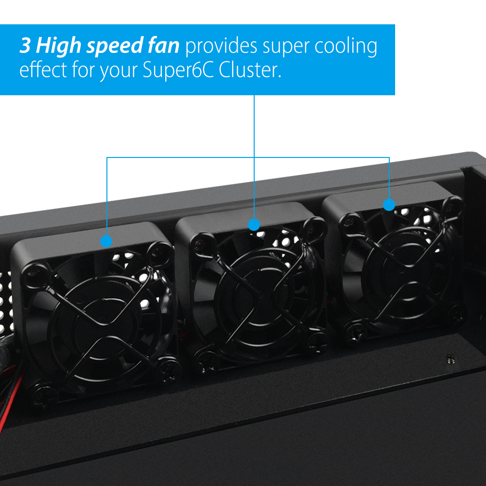
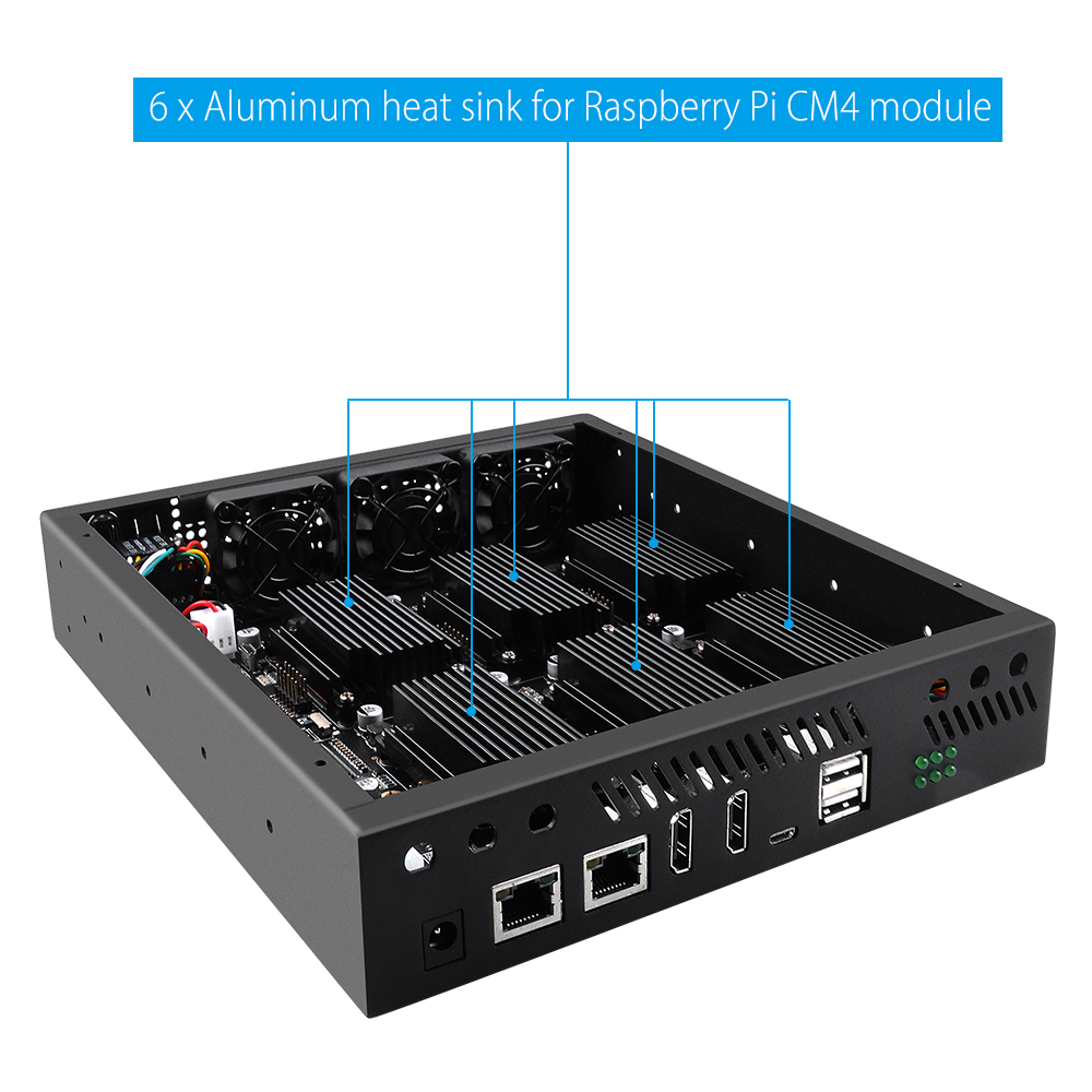
Equipped with three high-speed 12V cooling fans and six dedicated aluminum heatsinks, the enclosure creates steady cross-flow airflow across all compute modules and M.2 SSDs, ensuring thermal stability even under continuous multi-node computing workloads.
Specifications
| Specification | Details |
|---|---|
| Form Factor | Mini-ITX Enclosure |
| Motherboard Support | DeskPi Super6C Motherboard ONLY |
| Max Motherboard Size | Standard Mini-ITX (170 × 170 mm) |
| Storage Compatibility | Supports M.2 NVMe SSDs, M.2 SATA SSDs, and TF/MicroSD cards installed on Super6C |
| Cooling | 3× 12V High-Speed Fans (6000 RPM) + 6× Custom CM4 Aluminum Heatsinks |
| Enclosure Dimensions | 270 × 235 × 65 mm |
| Weight | Net: 1.04 kg / Gross: 1.23 kg |
| SKU | DP-0010 |
Fan Specifications
- Operating Voltage: 12V DC
- Current: 0.05A
- Rotational Speed: 6000 RPM
- Airflow: 4.96 CFM
- Noise Level: 21.16 dBA
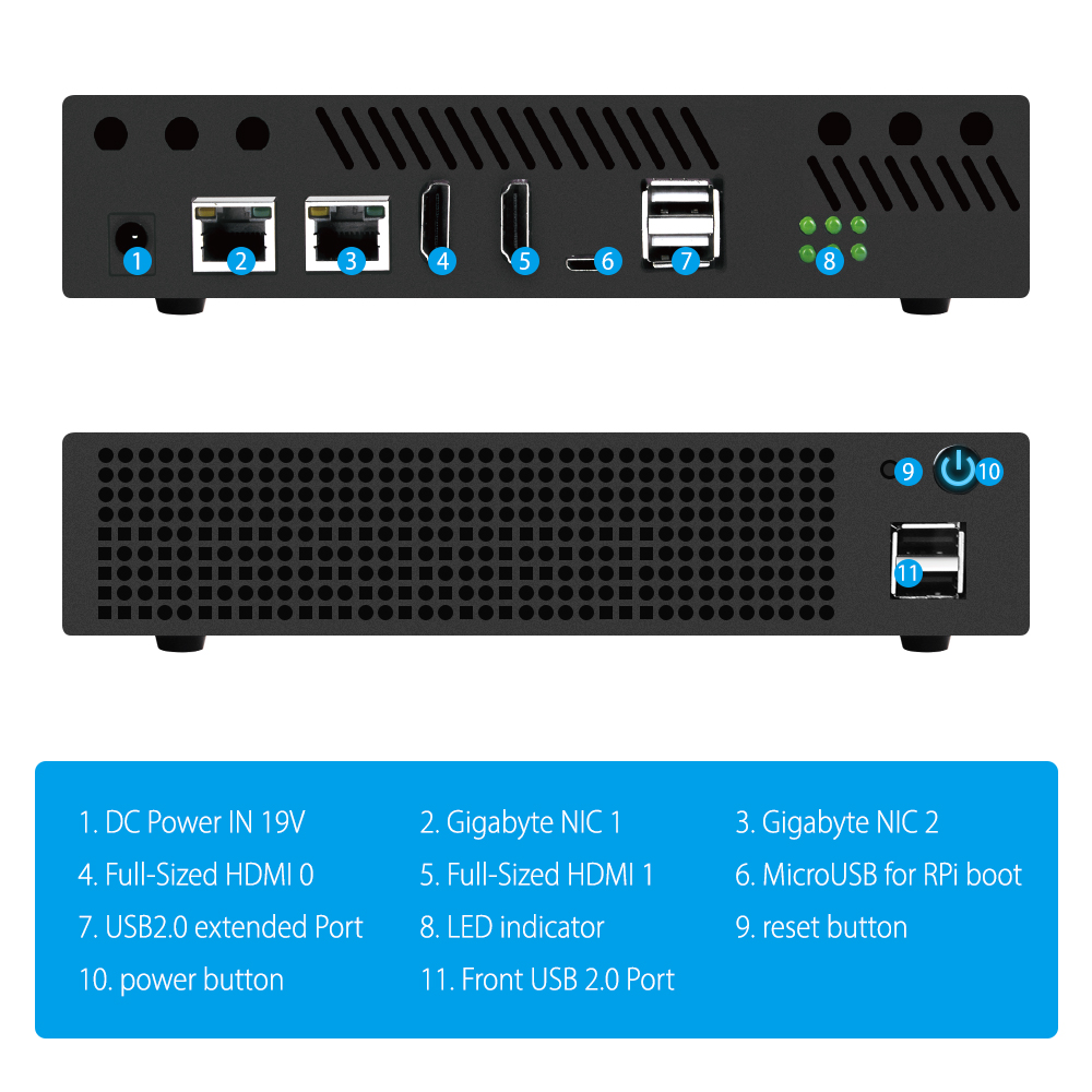
Front Panel Controls & Indicators
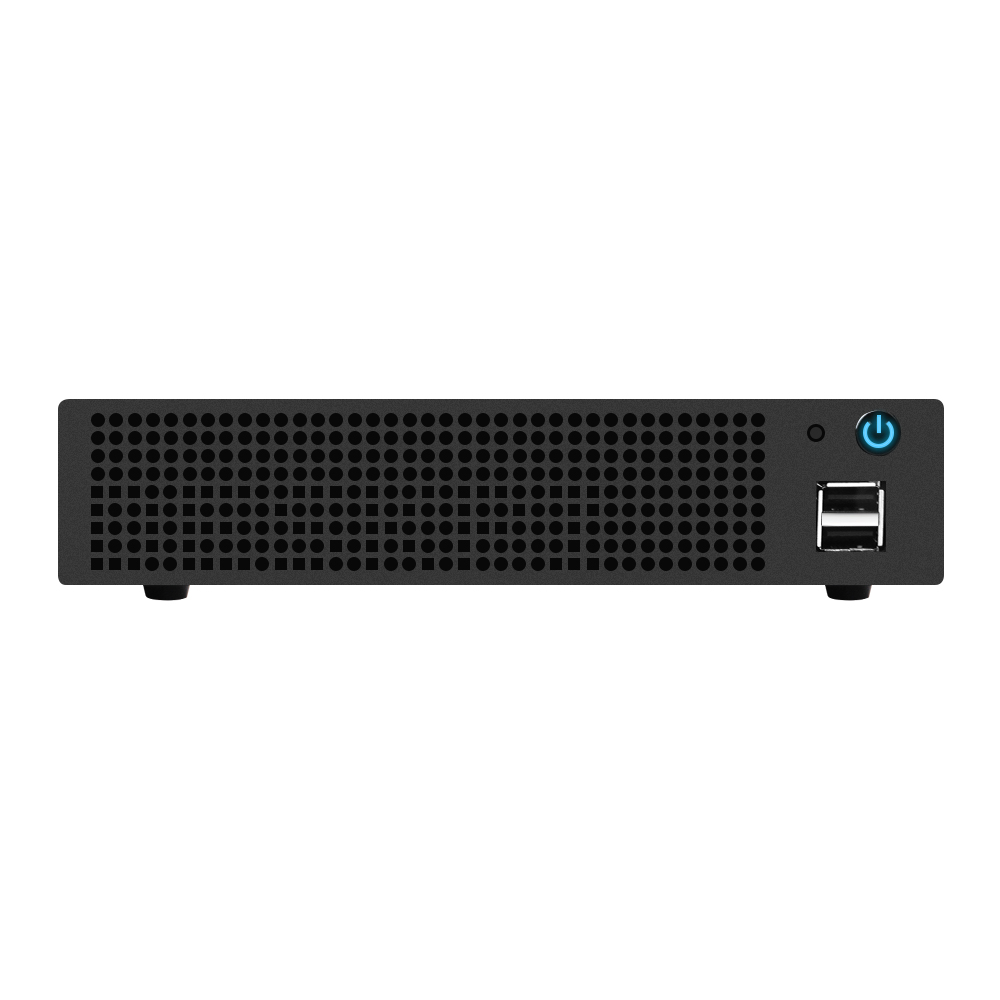

Power Button
- Short press: Turn on the Super6C motherboard and all powered nodes.
- Long press (5 seconds): Force power off the motherboard.
Reset Button
Pressing the Reset button triggers an immediate hardware reset for all 6 CM4 nodes simultaneously. Unsaved in-memory data across your cluster nodes will be lost. Use caution when pressing this button during production or multi-node cluster operations.
Internal Layout & Header Wiring
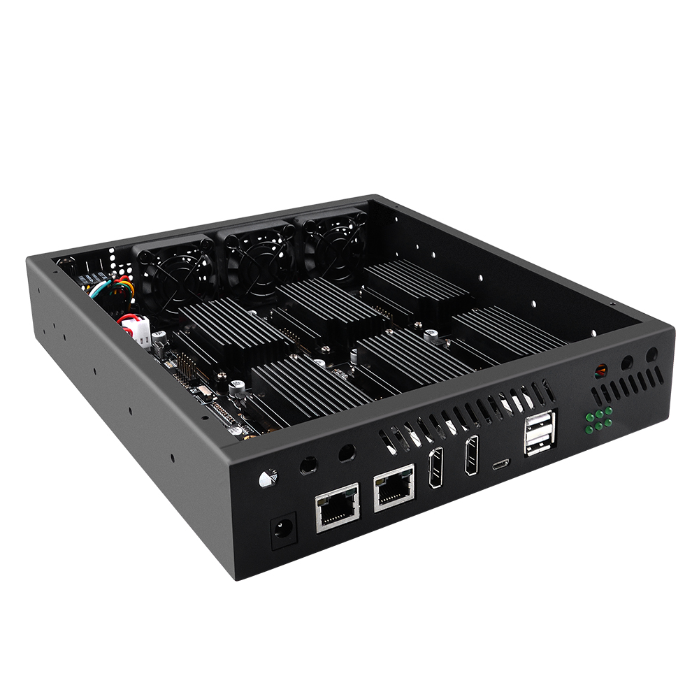
The front panel harness routes power, reset, status LEDs, and front USB expansion to the Super6C motherboard:
- Front USB Port: Connect the internal USB header cable to the Super6C J6 pin header.
- Cooling Fans: Connect the 3 fan power cables to the motherboard headers labeled
FAN,FAN2, andFAN3. - Control Buttons & LEDs: Connect the front switch cable harness to the J18 pin header to enable the front power switch, reset switch, and power indicator LED.
Assembly Guide
Follow these sequential steps to install your Super6C motherboard into the ITX chassis:
Step 1: Install CM4 Modules & Heatsinks
- Seat each Raspberry Pi CM4 module securely into its respective Hirose board-to-board connector on the Super6C motherboard.
- Peel off the protective film from the thermal pad and apply the pad to the CM4 Broadcom SoC.
Thermal Pad Sizing
The included aluminum heatsink is shaped to accommodate CM4 models with onboard eMMC and Wi-Fi modules, as well as Lite models. Place the thermal pad directly onto the center CPU.
- Secure the aluminum heatsink using the supplied M2.5 screws from the underside.
- Repeat for all 6 CM4 modules.
Step 2: Mount Motherboard into Chassis
- Lower the Super6C motherboard into the metal chassis and align it with the standoffs.
- Secure the motherboard using the provided flat-head mounting screws.
- Plug the front USB header cable into the J6 pin header on the Super6C.
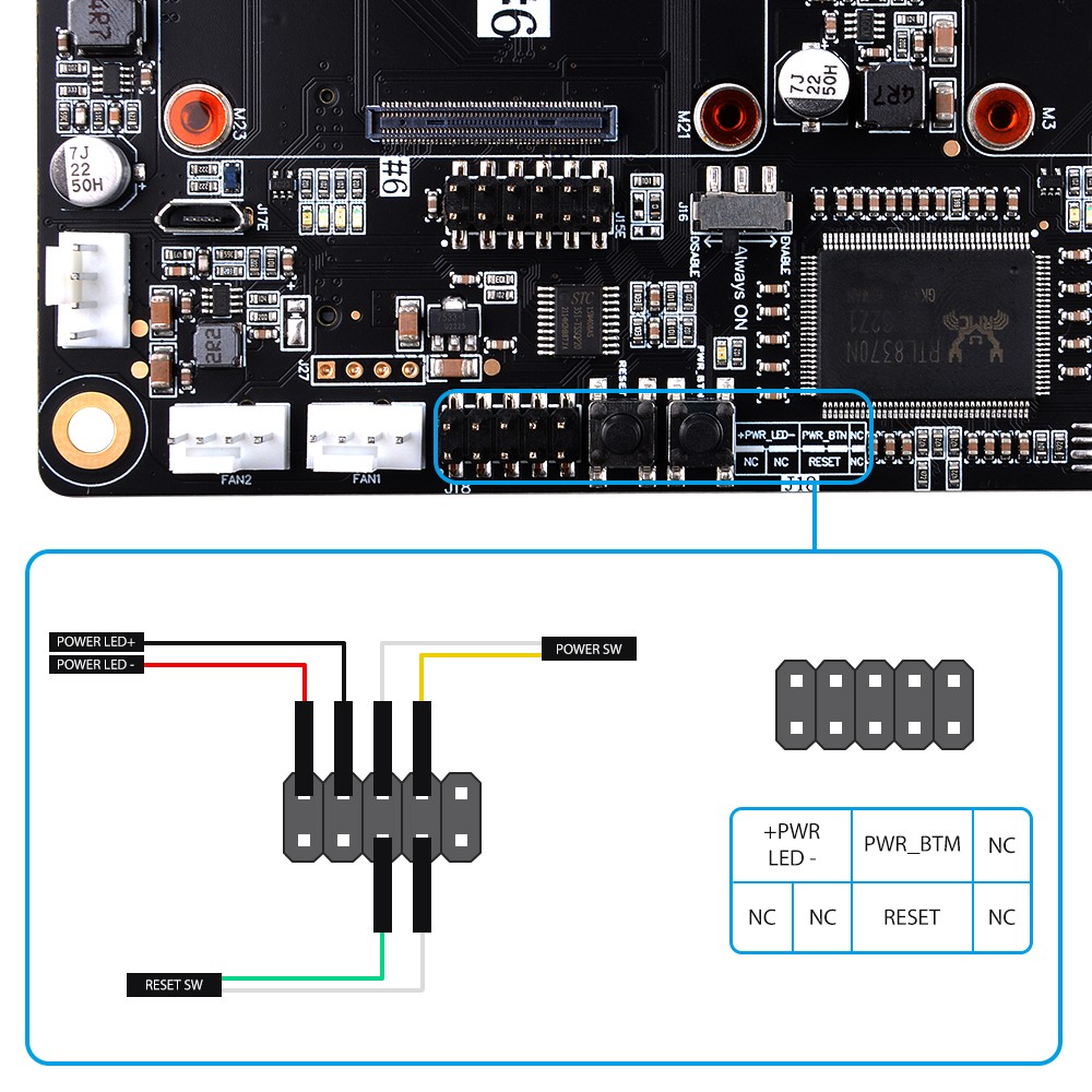
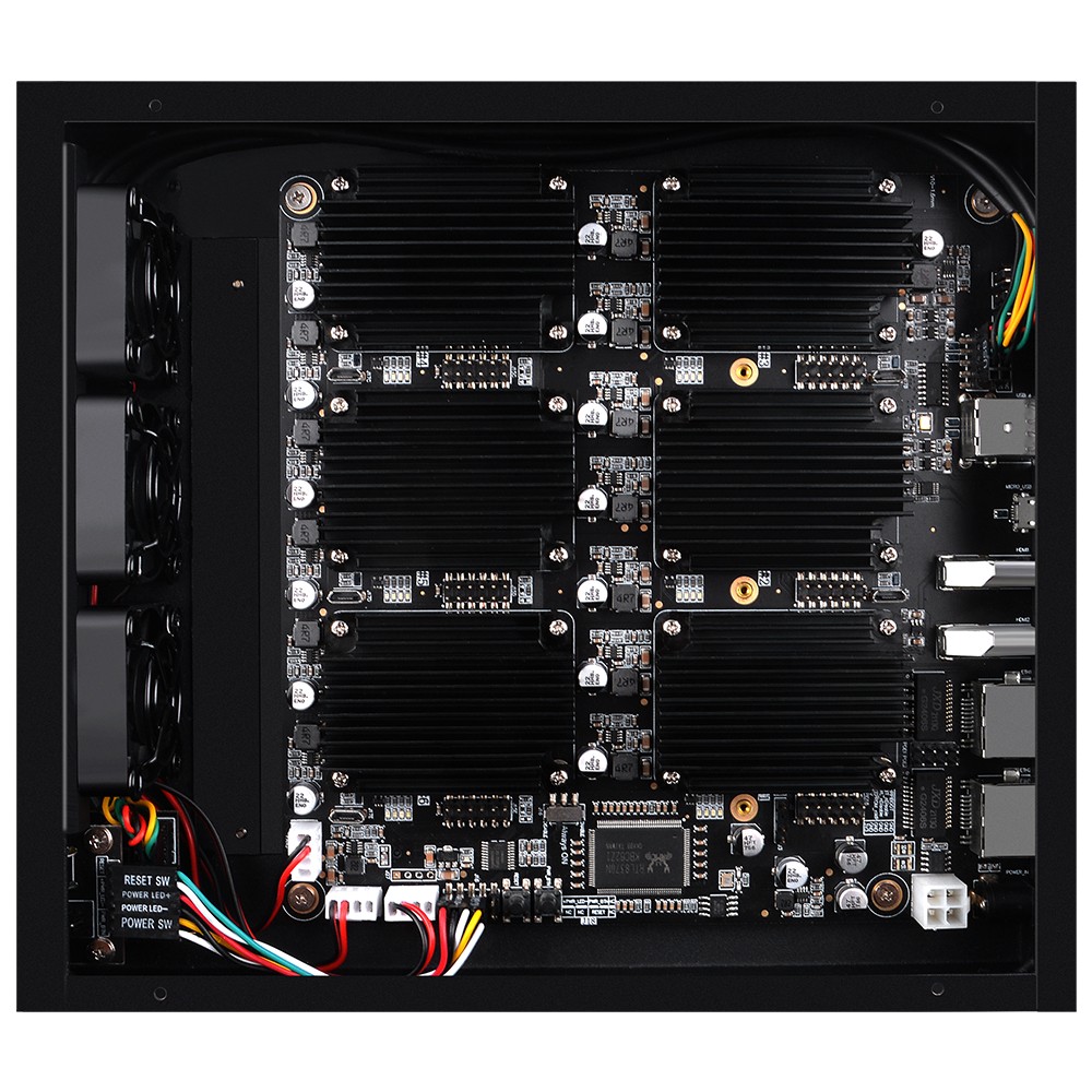
Step 3: Connect Fans and Front Panel Wiring
- Connect the 3 cooling fans to motherboard fan headers (
FAN1,FAN2,FAN3). - Attach the power switch, reset switch, and power LED leads to pin header J18.
Step 4: Attach Acrylic Top Panel
- Remove the protective film from both sides of the transparent acrylic top panel.
- Align the acrylic panel with the mounting pillars and tighten the top screws.
Related Products & Ecosystem
- DeskPi Super6C Cluster Board (DP-0008) — The 6-node CM4 Mini-ITX motherboard engineered for this chassis.
- 10-inch Mini-PC Tray (DP-0073) — Allows mounting the Super6C ITX case into a DeskPi RackMate 10-inch rack.
- DeskPi Super4C Cluster Board (DP-0040) — 4-node Raspberry Pi CM5 cluster motherboard.