DeskPi Mini Cube (DP-0019)
Description
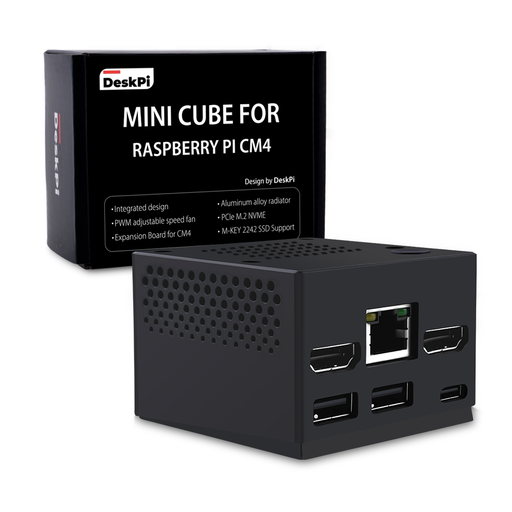
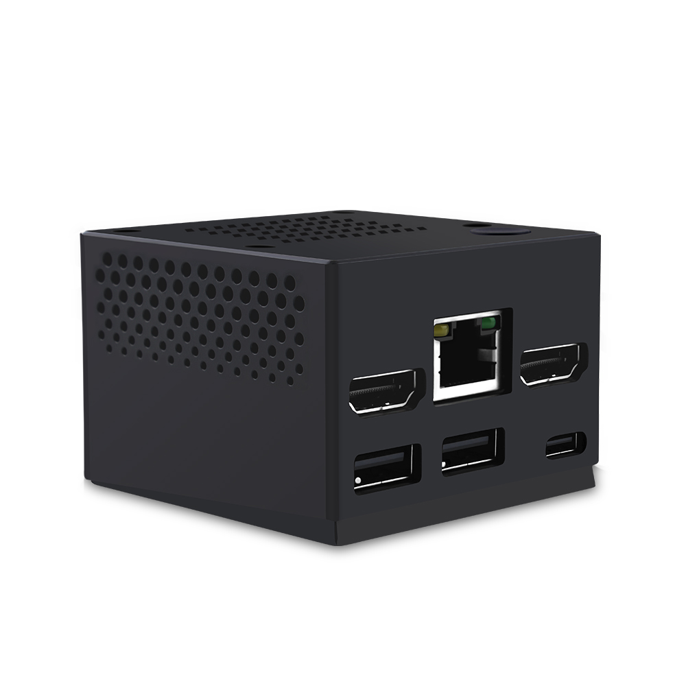
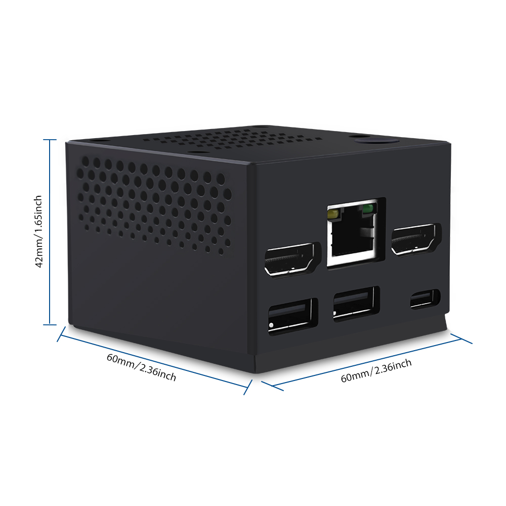
DeskPi Mini Cube for Raspberry Pi CM4 is a case with a miniature appearance and extremely portable features.
Note: Only supports Raspberry Pi CM4 module
The device provides a mini aluminum alloy radiator and integrates a silent fan that supports PWM speed regulation.
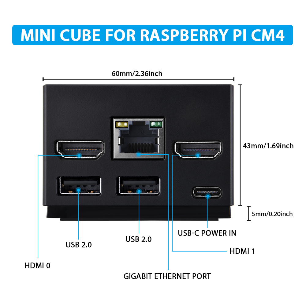
The bottom board provides a wealth of interfaces, supporting dual full-size HDMI interfaces, RJ45 Ethernet interfaces, 2x OTG USB port, and one PCIe interface supports M.2 NVME SSD M-KEY 2242 external storage.
The DIP switch on the back provides the special pins needed to configure the Raspberry Pi CM4 module. (On Compute Module 4 EMMC-DISABLE / nRPIBOOT (GPIO 40) must be fitted to switch the ROM to usbboot mode.)
Otherwise, the SPI EEPROM bootloader image will be loaded instead.
The 40Pin GPIO lead out and reserved RTC clock battery interface.
Features
- Integrated design
- Aluminum alloy radiator with PWM adjustable speed fan
- Power button
- 2 x Full-size HDMI ports
- 2 x OTG USB2.0 port
- 1 x PCIe M.2 NVME M-KEY 2242 SSD slot
- 1 x 40 Pin GPIO lead out
- 1 x DIP switch for mode change (CM4 function change)
- 1 x Onboard PCF85063 I2C RTC module
- 5V USB-C Port Power IN
Gallery

IPEX Antenna Specifications
- Center Frequency: 2400–2500 MHz & 4900–5900 MHz
- Connector: IPEX1
- Antenna Cable: 1.13 Coaxial cable with plastic jacket
- Impedance: 50 Ohm
- Gain: ~3 dBi
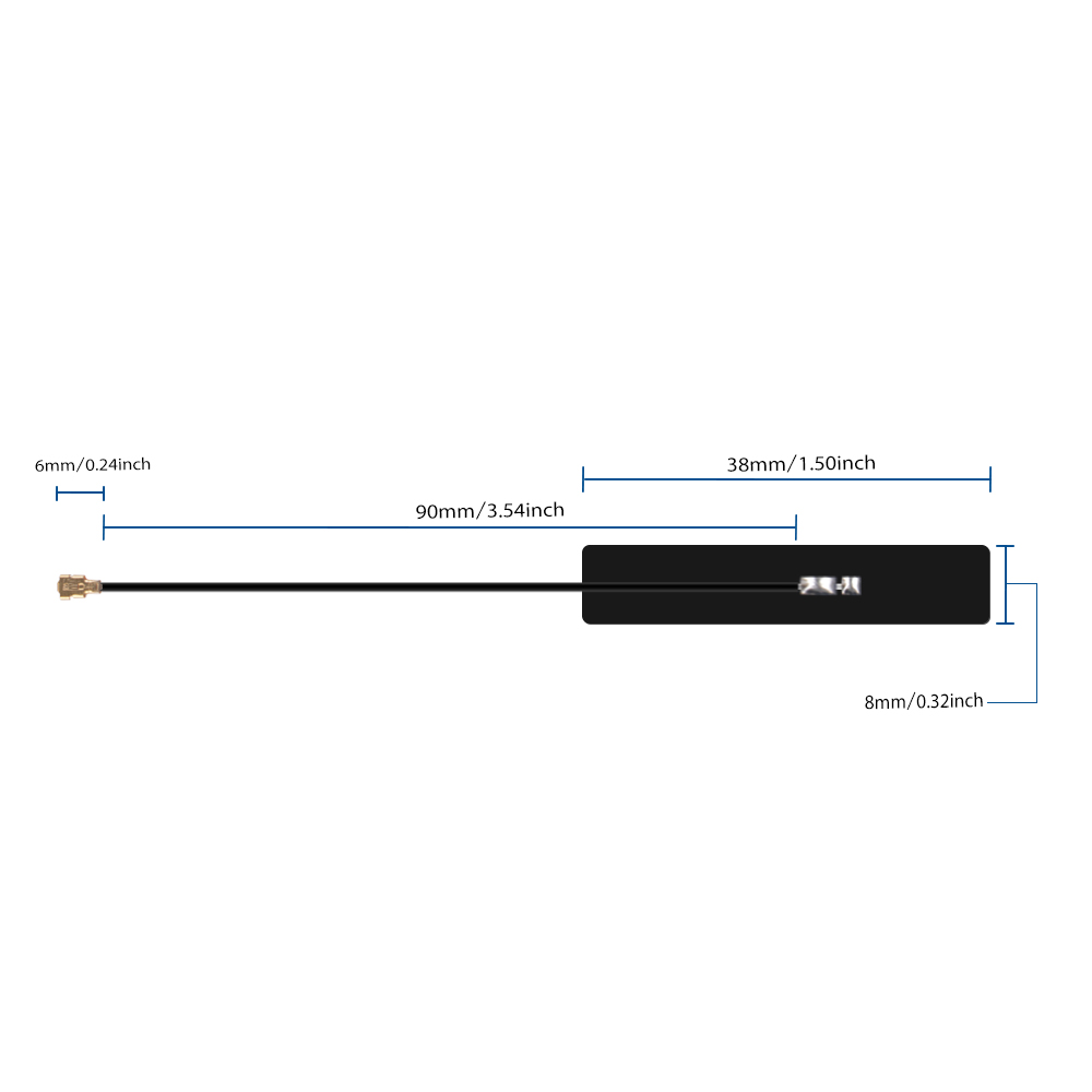
IPEX1 internal antenna structure
Install IPEX Antenna
Adhere the antenna as shown in the diagram. Remove the protective backing tape and paste the flexible antenna flat against the inside wall of the enclosure:
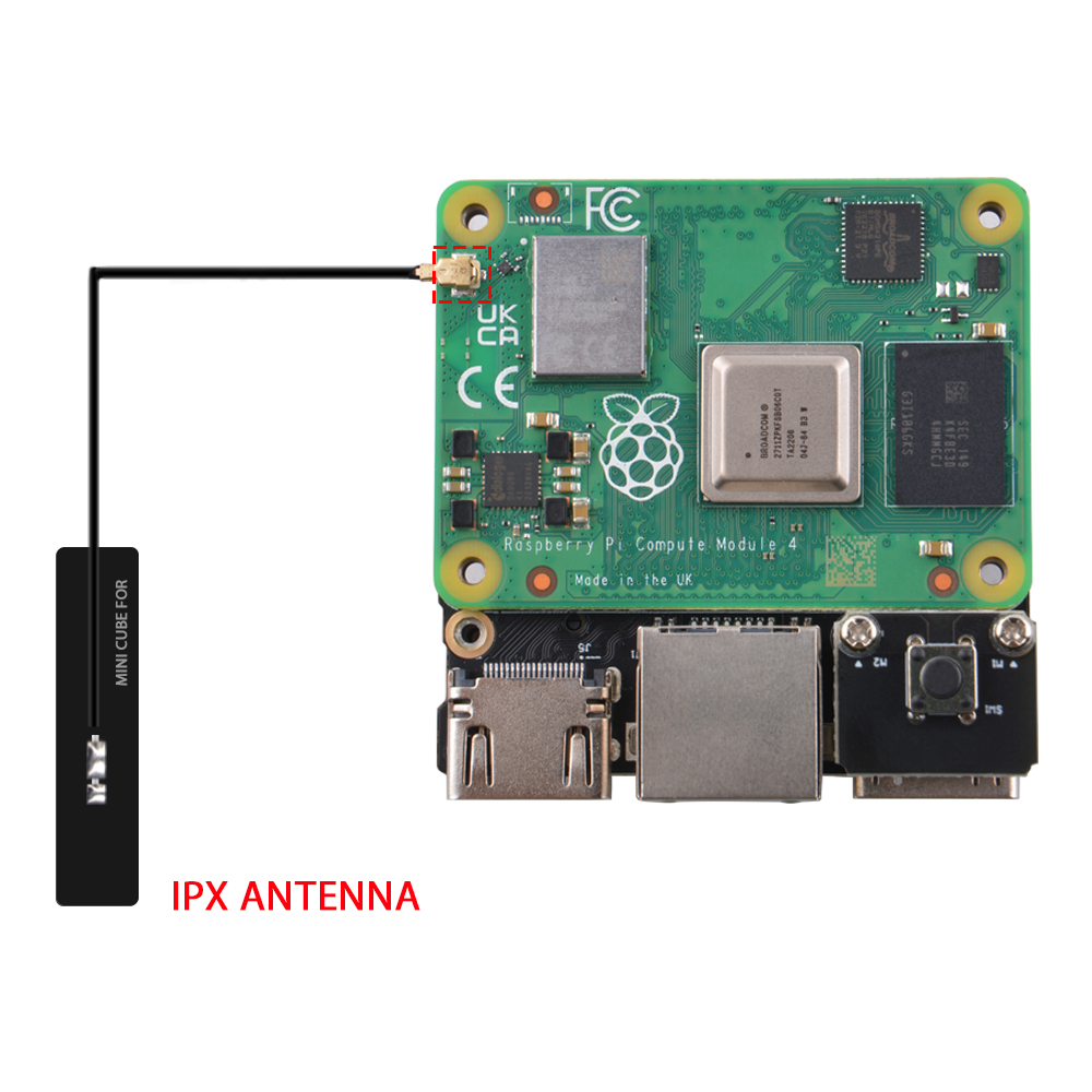
IPEX antenna placement inside enclosure
RTC Battery Information
The RTC backup battery is not included in the standard package and requires separate purchase.
- Recommended Model:
CR1220 3Vcoin cell withZH1.252-pin connector.
How to Assemble
CM4 Module Installation
- Step 1: Loosen the four screws on top of the Mini Cube.
- Step 2: Remove copper pillars and apply the thermal pad onto the Raspberry Pi CM4 module.
Note: Peel off the protective film on both sides of the thermal pad. Align the CM4 high-density connectors carefully with the carrier board before pressing firmly.
- Step 3: Fix the aluminum heatsink onto the CM4 module with the copper standoffs.
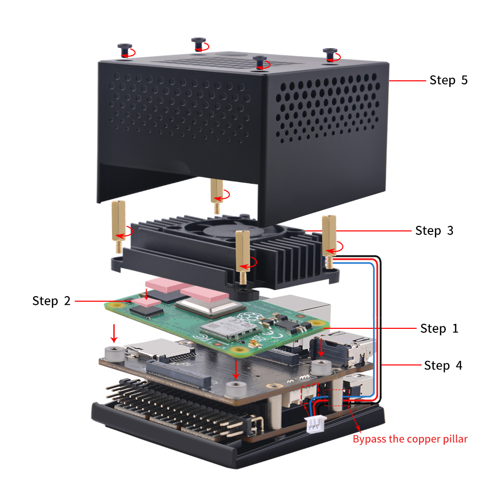
CM4 installation and heatsink alignment
[Optional] Install M.2 NVMe SSD (M-Key 2242)
- Remove the screws on the bottom plate of the Mini Cube and remove the SSD carrier daughter board.
- Insert the M.2 NVMe SSD into the socket at a 30-degree angle and secure it with the mounting screw.
- Align the daughter board with the header pins on the mainboard and reconnect securely.
- Replace the bottom cover plate and tighten all screws.
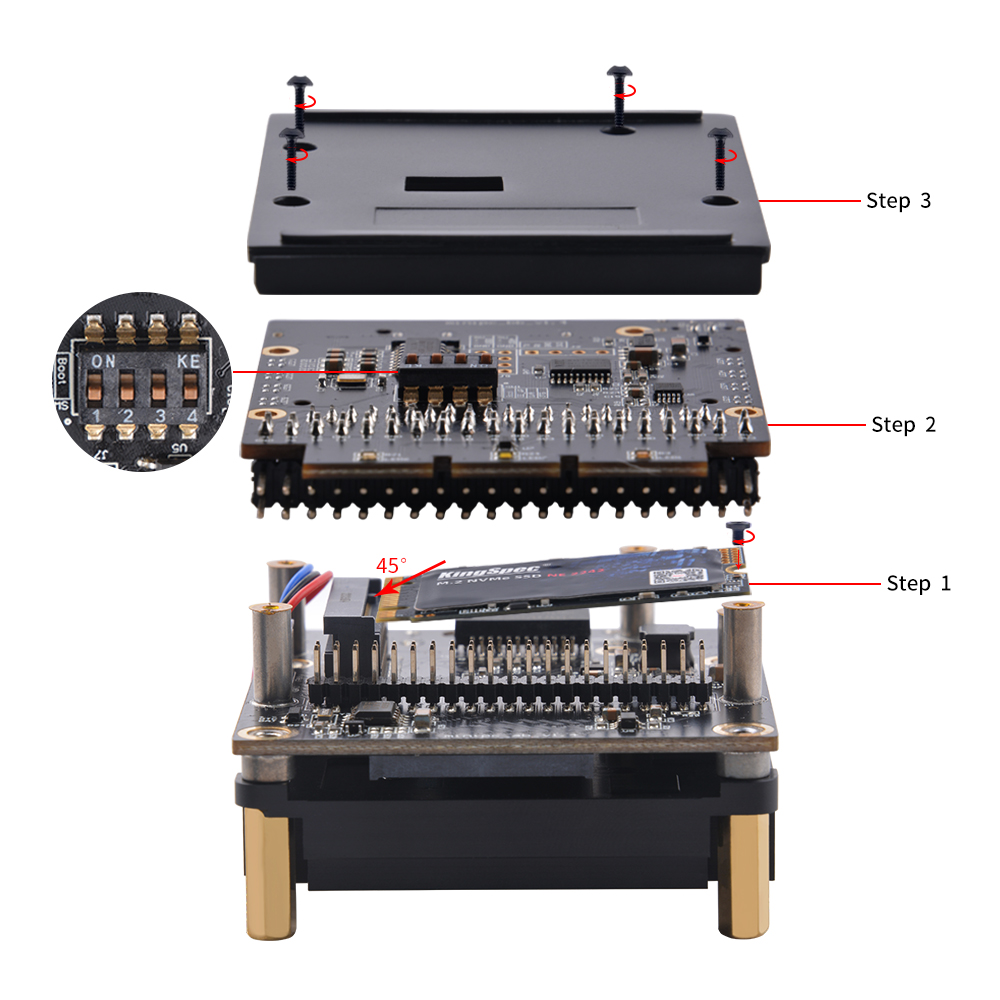
Bottom carrier board and DIP switch configuration
Functionality of power button:
- Short Press:
Power on - Long Press:
Power off (Cutoff power)
Please
NOTEthat if you have not shutdown the system, do not use long press to halt system, it will damage your system, it may cause kernel panic or lost file which are not saved yet.
- Correct Operation: Shutdown system in terminal or desktop, and then long press the button to cut off power.
DIP Switch Functionality
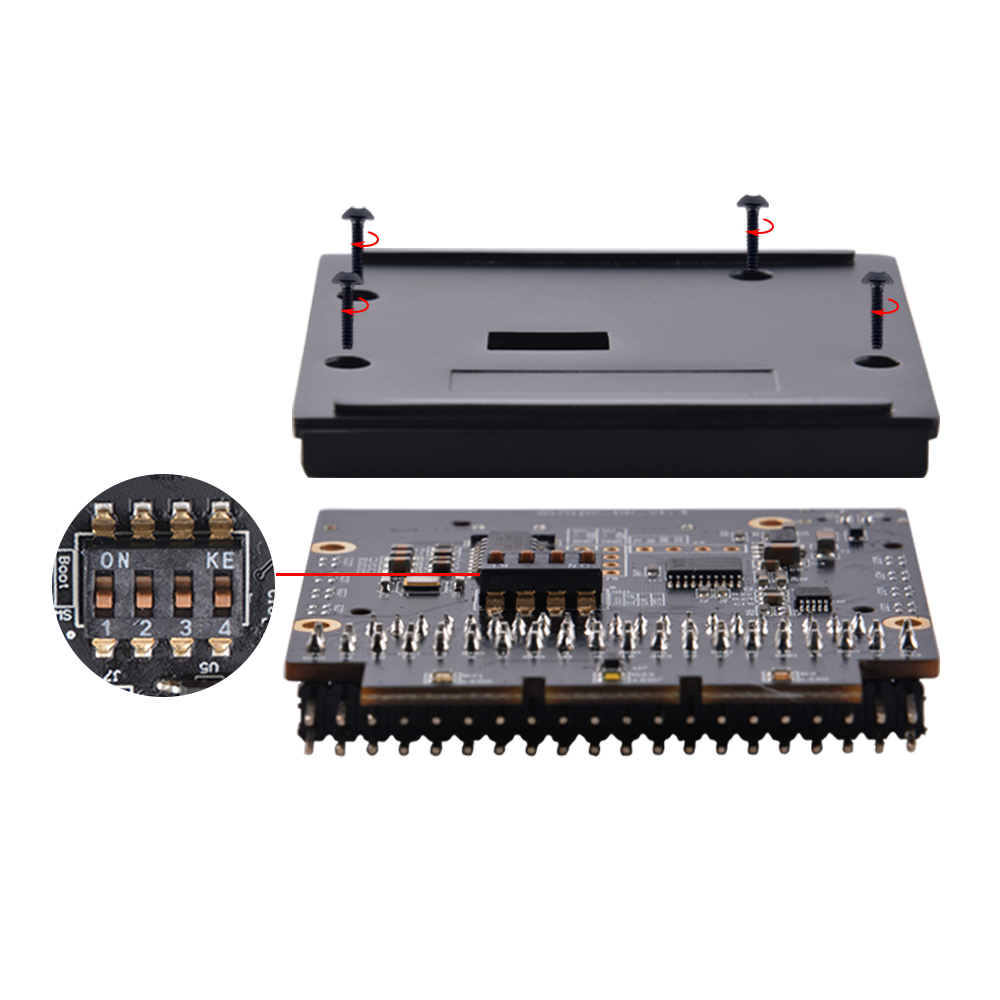
DIP Switch Pinout
The rear DIP switch configures CM4 hardware modes:
- Pin 1: USB OTG Pull Up
- Pin 2: Reserved (Unattended)
- Pin 3: EEPROM_nWP (EEPROM write protection)
- Pin 4: nRPIBOOT (eMMC flashing mode switch)
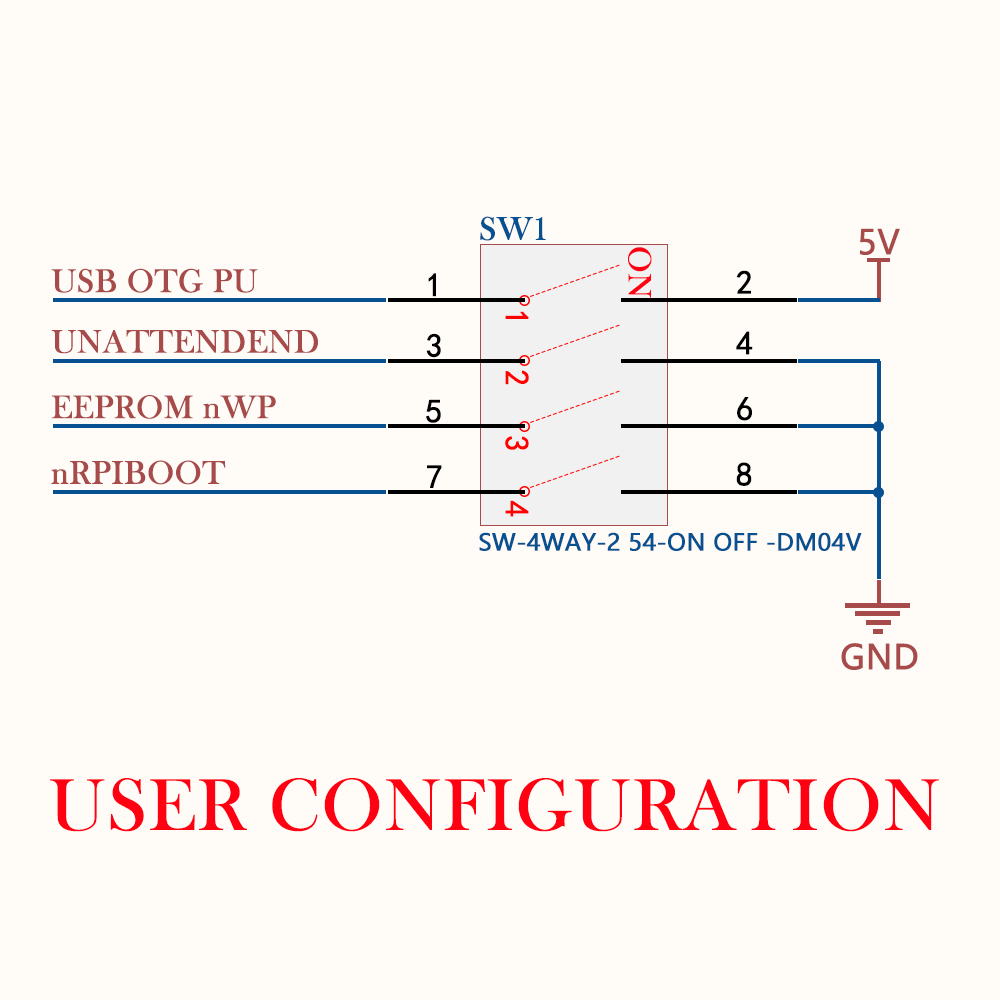
DIP switch pin distribution and configuration
If you are using Raspberry Pi CM4 with EMMC onboard. please refer to this URL: How to flash the Compute Module in section “Flashing the Compute Module eMMC”
Hardware write-protection must be enabled via software and then locked by pulling the EEPROM_nWP pin low.
How to enable USB2.0 ports besides the USB-C port?
Assume that you are using Raspberry Pi OS (64bit/32bit).
- The latest official image which you can download from:
www.raspberrypi.com/softwarewill automatically addingotg_mode=1in /boot/firmware/config.txt file, so you don't need to modify any parameter in /boot/firmware/config.txt file.
How to Update EEPROM Firmware on Raspberry Pi Compute Module 4 (CM4)
Overview
Unlike earlier Compute Modules, the CM4 uses an EEPROM bootloader stored in on-board storage rather than the boot partition. This means it requires different update procedures compared to standard Raspberry Pi boards.
Prerequisites
| Item | Description |
|---|---|
| Host PC | Linux, macOS, or Windows PC with USB port |
| CM4 + IO Board | CM4 mounted on an official CM4 IO Board or compatible carrier |
| USB Cable | USB-C or micro-USB cable to connect IO Board to host |
| usbboot tools | Raspberry Pi usbboot utility installed on the host |
Install usbboot (Host PC)
# Clone the official usbboot repository
git clone --depth=1 https://github.com/raspberrypi/usbboot
cd usbboot

# Build (Linux/macOS)
make

# Install dependencies if needed (Debian/Ubuntu)
sudo apt install libusb-1.0-0-dev
Method 1: Flash Bootloader EEPROM via USB (Recommended)
This method directly writes the bootloader EEPROM using rpiboot in recovery mode. It is the most reliable method for CM4.
Step 1: Hardware Setup
- Mount the CM4 onto the IO Board.
- Ensure the
EEPROM_nWPpin is NOT pulled low (write-protection must be disabled). - Connect the IO Board's USB slave port to your host PC.
- Do NOT insert an SD card or eMMC storage if you want to target the EEPROM directly.
- Power on the IO Board.
Step 2: Flash the EEPROM
Run the recovery command from the usbboot directory:
cd usbboot
sudo ./rpiboot -d recovery
This writes recovery/pieeprom.bin to the CM4's bootloader EEPROM.
Step 3: Re-enable Write Protection (Optional)
Once flashing completes successfully, you may pull EEPROM_nWP low again to prevent accidental modification.
Method 2: Self-Update from a Running OS
If your CM4 is already booting from eMMC, USB, or network, you can enable self-update mode. However, this method carries a risk.
⚠️ Warning: Self-update mode does not update the bootloader atomically. If a power failure occurs during the EEPROM update, you could corrupt the EEPROM.
Why CM4 Disables rpi-eeprom-update by Default
On CM4, the rpi-eeprom-update service is disabled by default because the eMMC is not removable, and an invalid recovery.bin file could brick the system.
Enable Self-Update
- Add the following to your
config.txtor bootloader configuration:
ENABLE_SELF_UPDATE=1
- Reboot the CM4. The bootloader will check for updates from the boot media (eMMC, USB MSD, or network boot).
Method 3: Update from Raspberry Pi OS (If Running)
If you have Raspberry Pi OS running on the CM4 and want to check the current EEPROM version:
# Check current EEPROM status
sudo rpi-eeprom-update

# Update to latest stable (only works if self-update is enabled or on supported platforms)
sudo rpi-eeprom-update -a
Note: On some platforms (e.g., Home Assistant Yellow with CM4), firmware updates via
rpi-eeprom-updatemay be blocked withunsupported_boot_device. In such cases, use therpibootmethod instead.
Important Best Practices
Before deploying CM4 in production, Raspberry Pi recommends:
- Select a specific bootloader release and verify every CM4 has that release.
- Configure
BOOT_ORDERto define the boot device priority (eMMC → USB → NVMe → Network, etc.). - Enable hardware write-protection (
EEPROM_nWPpulled low) on production units to prevent unauthorized modification.
Example Bootloader Configuration
Create or edit boot.conf before flashing:
[all]
BOOT_UART=0
WAKE_ON_GPIO=1
POWER_OFF_ON_HALT=0
BOOT_ORDER=0xf2641   # eMMC → USB → NVMe → Network → Loop
ENABLE_SELF_UPDATE=1
Then use rpi-eeprom-config to apply it:
sudo rpi-eeprom-config --out pieeprom-new.bin --config boot.conf pieeprom.bin
Troubleshooting
| Issue | Solution |
|---|---|
rpiboot hangs or can't detect CM4 | Check USB cable, ensure CM4 is powered, try a different USB port |
| EEPROM update succeeds but CM4 won't boot | Verify BOOT_ORDER is correct; newer silicon may require newer EEPROM (≥ 2026-01-09 for recent batches) |
unsupported_boot_device error | Use rpiboot -d recovery method instead of OS-level update |
| Write-protected error | Ensure EEPROM_nWP is not pulled low during flashing |
References
Updating CM4 EEPROM Firmware with DeskPi Mini Cube
DIP Switch Configuration
The DeskPi Mini Cube has a 4-position DIP switch on the back that controls key CM4 signals. Here is the pinout:
| Switch | Function | Description |
|---|---|---|
| 1 | USB OTG Pull UP | Enables USB OTG pull-up resistor |
| 2 | UNATTENDED | Unattended boot mode |
| 3 | EEPROM_nWP | EEPROM Write Protection (low = protected) |
| 4 | nRPIBOOT | eMMC Boot Disable (low = usbboot mode) |
Step-by-Step: Flash EEPROM via USB (rpiboot)
1. Set DIP Switches for USB Boot Mode
To put the CM4 into rpiboot mode (required for EEPROM flashing), configure the switches before powering on:
| Switch | Position | Reason |
|---|---|---|
| 1 | OFF | Not needed for EEPROM update |
| 2 | OFF | Not needed |
| 3 | OFF | Disable write-protection (EEPROM_nWP high → EEPROM writable) |
| 4 | ON | Enable nRPIBOOT (pull GPIO 40 low → ROM enters usbboot mode) |
⚠️ Critical: Switch 4 must be ON before power is applied, and switch 3 must be OFF to allow EEPROM writing.
2. Connect Hardware
- Connect a USB-C cable from the Mini Cube's USB-C port to your host PC (Linux/macOS/Windows).
- Connect USB-C power to the Mini Cube's power input.
- Power on the Mini Cube.
3. Run rpiboot on Host PC
On your host computer, clone and run the official usbboot tool:
# Linux / macOS
git clone --depth=1 https://github.com/raspberrypi/usbboot
cd usbboot
make

# Flash the EEPROM with the recovery firmware
sudo ./rpiboot -d recovery
This will write recovery/pieeprom.bin to the CM4's SPI EEPROM.
4. Custom EEPROM Configuration (Optional)
If you want to customize bootloader settings (e.g., BOOT_ORDER), edit recovery/boot.conf first, then regenerate the EEPROM image:
cd recovery
# Edit boot.conf as needed
./update-pieeprom.sh
cd ..
sudo ./rpiboot -d recovery
Step-by-Step: Normal Boot Mode (After Update)
Once the EEPROM is flashed, revert the DIP switches to boot from eMMC or NVMe:
| Switch | Position |
|---|---|
| 1 | OFF |
| 2 | OFF |
| 3 | ON |
| 4 | OFF |
Then power-cycle the Mini Cube.
Troubleshooting
| Issue | Check |
|---|---|
rpiboot cannot detect device | Verify switch 4 is ON before power-on; try a different USB cable/port |
| EEPROM write fails | Ensure switch 3 is OFF (write-protection disabled) |
| Green LED stays ON after disconnecting USB | Indicates nRPIBOOT GPIO is still high — check switch 4 is ON |
| Need to re-flash eMMC OS | Use sudo ./rpiboot -d mass-storage-gadget to mount eMMC as USB drive |
Summary
| Task | Switch 3 (EEPROM_nWP) | Switch 4 (nRPIBOOT) |
|---|---|---|
| Flash EEPROM | OFF (writable) | ON (usbboot mode) |
| Normal Boot | ON (protected) | OFF (boot from storage) |
How to enable fan automatically?
** Assume that your operating system is Raspberry Pi OS (32bit/64bit) **
Official Fan setting
- Open a terminal and typing following command:
sudo raspi-config
Navigate to Performance Options -> P4 Fan -> Yes -> 14 -> 60 -> yes -> finish -> reboot Raspberry Pi.
The fan is support PWM signal control via GPIO14 which is physical pin 12(TXD), it will spinning when the CPU temperature is above 60 degree.
and also you can write your code to control the fan via GPIO14, sending PWM signal will trigger the fan spinning.
Control Fan manually
Demo code
- Here is a demo code for controlling fan speed by using python script.
 #!/usr/bin/python3

import RPi.GPIO as GPIO
import time
import subprocess

GPIO.setmode(GPIO.BCM)
GPIO.setup(14, GPIO.OUT)
pwm = GPIO.PWM(14,100)

print("\nPress Ctrl+C to quit \n")
dc = 0
pwm.start(dc)

try:
    while True:
        temp = subprocess.getoutput("vcgencmd measure_temp|sed 's/[^0-9.]//g'")
        if round(float(temp)) >= 45:
            dc = 100
            pwm.ChangeDutyCycle(dc)
            print("CPU Temp:",float(temp)," Fan duty cycle:",dc)
            time.sleep(180.0)
        if round(float(temp)) >= 40:
            dc = 85
            pwm.ChangeDutyCycle(dc)
            print("CPU Temp:",float(temp)," Fan duty cycle:",dc)
            time.sleep(120.0)
        else:
            dc = 70
            pwm.ChangeDutyCycle(dc)
            print("CPU Temp:",float(temp)," Fan duty cycle:",dc)
            time.sleep(60.00)

except KeyboardInterrupt:
    pwm.stop()
    GPIO.cleanup()
    print("Ctrl + C pressed -- Ending program")
Then execute it:
python3 fan_control.py
How to enable onboard RTC module?
NOTE: RTC battery sock type: ZH1.25 The battery dose not include in the package, additional purchase required!! * Step 1. Modify /boot/config.txt file and adding following parameter:Save it and please reboot your Raspberry Pi.
-
Step 2. Check if RTC module has been recognized by Raspberry Pi. Execute following command in a terminal:
dmesg |grep i2c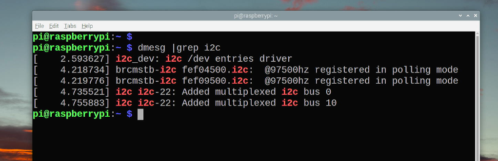 i2cdetect -y 10
NOTE: if command not found, please install
i2c-tools:sudo apt updatesudo apt upgrade -ysudo apt -y install i2c-tools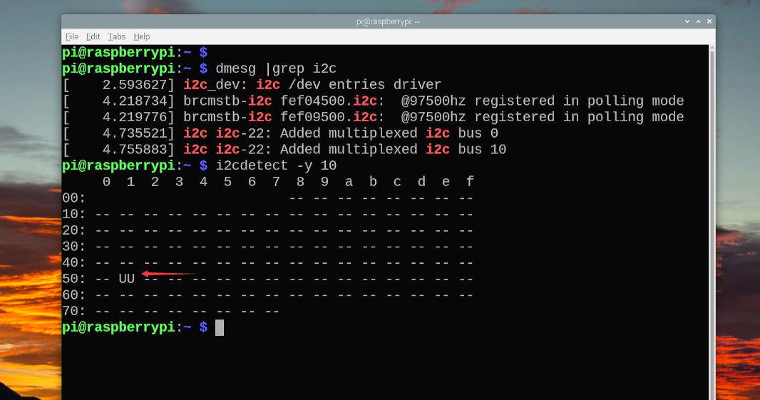
-
Step 3. Probe the module
rtc-pcf85063and check the kernel module status.modprobe rtc-pcf85063lsmod |grep rtc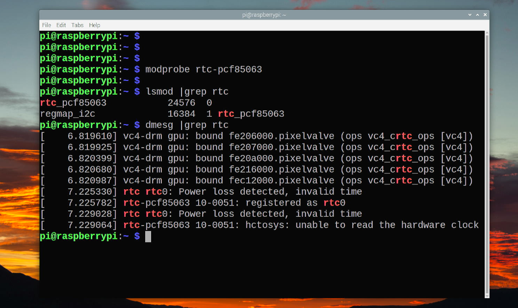
-
Step 4. Setting system date and sychronized system time to Hardware clock time.
** Check RTC time in command line.
cat /proc/driver/rtc
** Setting system time Syntax
date [-u|--utc|--universal] [MMDDhhmm[[CC]YY][.ss]]
For example:
sudo date -s 'tue oct 18 08:50:23 BST 2022'
or
sudo date 053118062023.22
It means setting system time to 2023.05.31 18:06:23.
** Sychronizing system time to HW clock time.
sudo hwclock -w
** Check RTC time and system time
sudo hwclock ; date
FAQ
- Q: Dose it support NVMe SSD booting? A: It has been tested, yes, it supports, but you may need to upgrade eeprom by using rpi-boot from official github repository.