DeskPi Super4C (DP-0040)
- Overview
- Hardware
- ESP32 & Web Controller
- Flash & Boot
- Cluster (Ansible)
Introduction
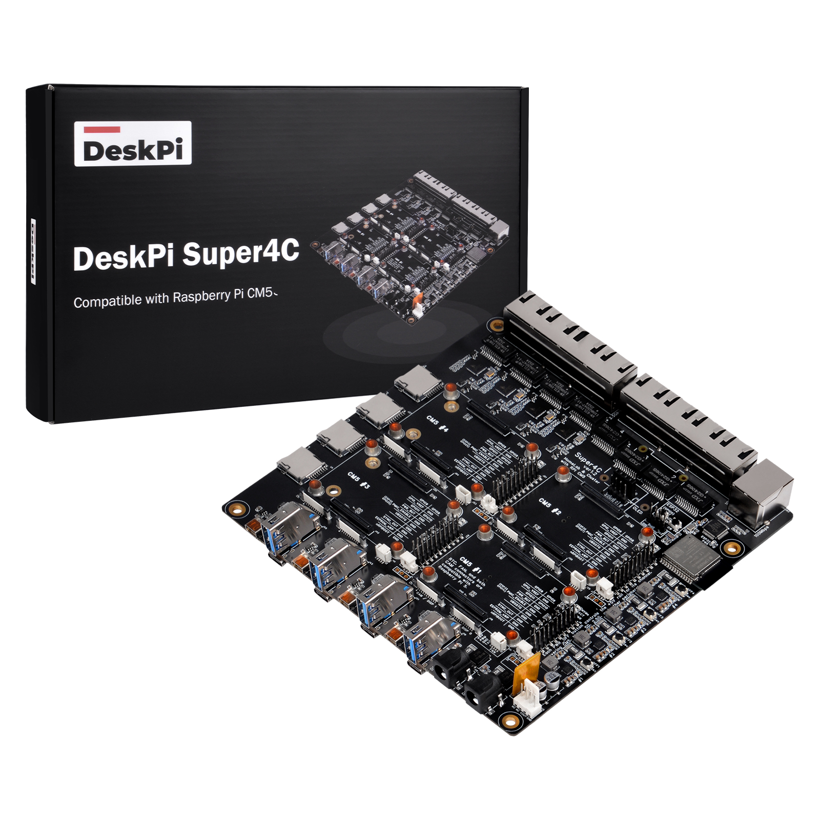
Super4C is a cluster-based hardware built on the Raspberry Pi CM5, supporting four channels of CM5 and extending almost all CM5 interfaces for powerful device connectivity. It also integrates an ESP32 module for remote management of the entire cluster. (Referred to as "the motherboard" throughout this document.)
Key Features
Power:
- External DC 12V–20V barrel connector (ID 2mm, OD 6.6mm); redundant dual-socket input (DC1/DC2); auto-selects higher voltage; reverse polarity protection + fuse circuits
- Four-channel independent DC/DC → 5V; independent per-channel PWR_OFF button; ~0.5s hardware power-on delay to prevent inrush current
Per CM5 channel (×4):
- 1× micro HDMI 2.0 interface
- 1× USB 3.0 (Port 0, max 0.9A output)
- 1× USB 2.0 Type-C (D+/D- only, no VBUS)
- 1× 1Gbps Ethernet (native RJ45)
- 1× 2.5Gbps Ethernet (via USB 3.0 Port 1 expansion)
- 1× microSD card (CM5 Lite only)
- 1× M.2 M-key PCIe 2280 slot
- 1× 4-pin JST-SH PWM fan
- 1× RTC battery interface
- 2× MIPI DSI/CSI-2 (22-pin 0.5-pitch FPC)
- Jumper header for eMMC/EEPROM disable; GPIO8–11 expansion
Management (ESP32):
- ESP32-WROOM-32E-N4 with 2.4GHz Wi-Fi + Bluetooth
- W5500 100Mbps wired network expansion
- UART download interface (J47); I2C expansion (J12/J16)
- Two INA3221 chips monitoring 6 voltage/current channels
Tested NVMe SSD Compatibility List
The M.2 2280 M-Key slots interface directly with the CM5 PCIe lane. The following high-performance SSD models have been verified:
| # | SSD Model | Interface | Capacity | Verification Status |
|---|---|---|---|---|
| 1 | Western Digital Black SN7100 | PCIe Gen 4.0 NVMe | 1 TB | ✓ Verified |
| 2 | Western Digital Black SN8100 | PCIe Gen 5.0 NVMe | 1 TB | ✓ Verified |
| 3 | Western Digital Black SN770 | PCIe Gen 4.0 NVMe | 2 TB | ✓ Verified |
| 4 | Fanxiang Jing Series | PCIe Gen 4.0 NVMe | 512 GB | ✓ Verified |
| 5 | Lexar NQ790 | PCIe Gen 4.0×4 NVMe | 2 TB | ✓ Verified |
| 6 | Samsung 990 PRO | PCIe Gen 4.0 NVMe | 2 TB | ✓ Verified |
Note: Due to the CM5 single PCIe Gen 2.0/3.0 x1 lane limitation, theoretical sequential read/write rates are capped accordingly.
Application Scenarios
The Super4C ships as a Mini-ITX board that drops straight into standard rack-mount enclosures and pairs with typical homelab networking and compute gear.
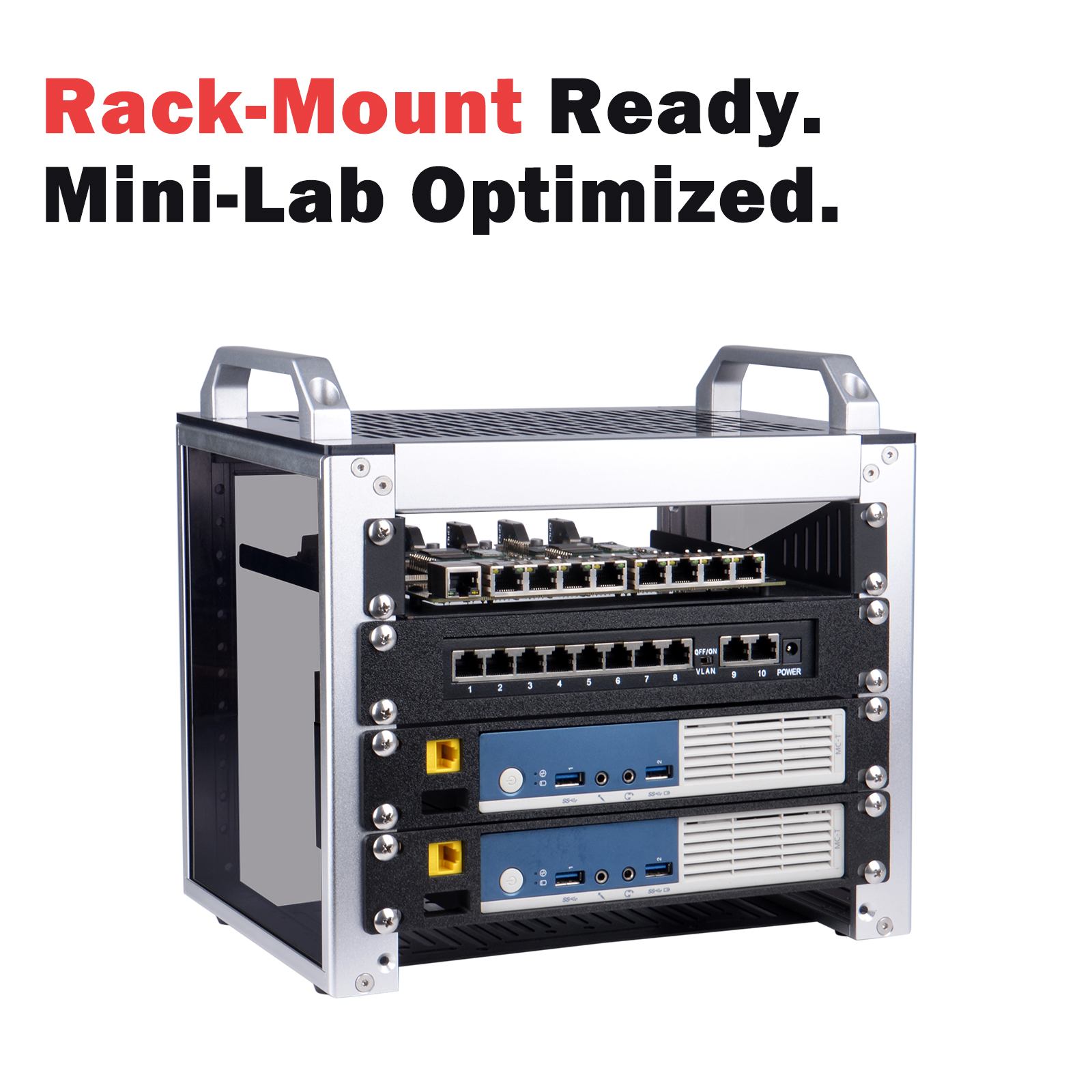
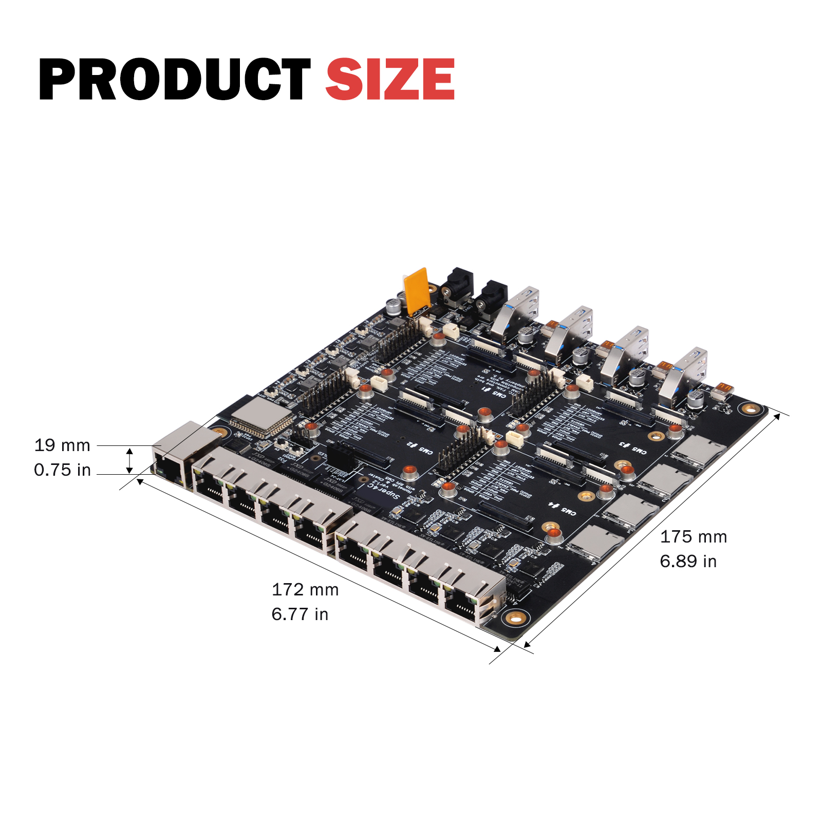
Diagram Block
Power Input
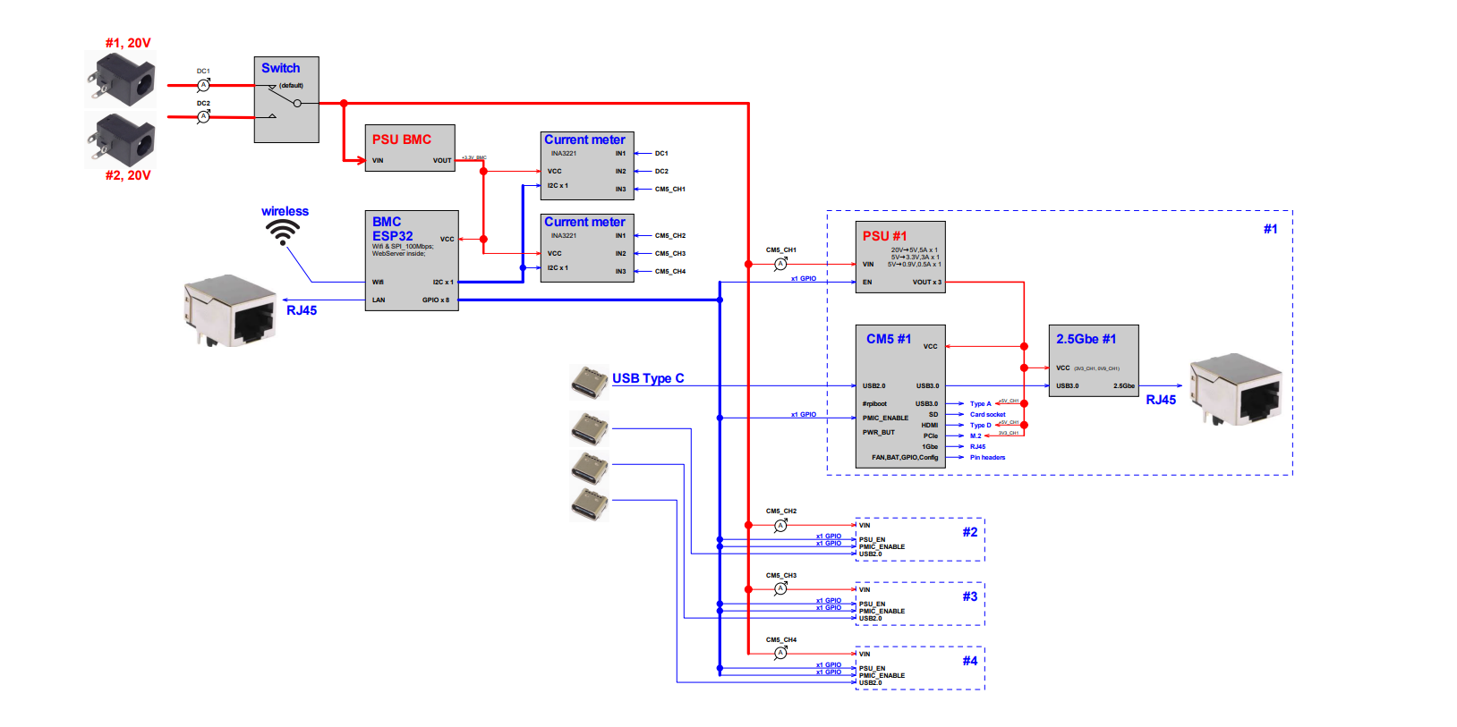
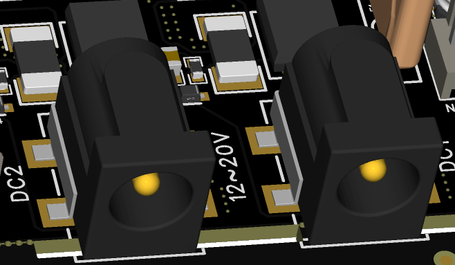
The main power input uses a barrel connector (ID 2mm, OD 6.6mm), DC 12V–20V. Two sockets (DC1/DC2) support redundant input; when two voltages differ, the board automatically uses the higher one.
Power Protection
Main power passes through protection, sampling, reverse polarity, and fuse circuits before powering internal components and the J15 fan output.
When connecting a fan, ensure its rated voltage matches the main power supply voltage.
5V DC/DC and Reset Buttons
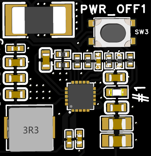
Four independent DC/DC channels supply 5V per CM5. Each channel has a PWR_OFF button (SW3/4/5/6) that independently resets that channel's power.
Voltage & Current Monitoring
Two INA3221 chips (I2C 0x40 and 0x41) monitor 6 channels:
- INA3221 #1 (0x40): DC1 input; DC2 input; 5V channel 1
- INA3221 #2 (0x41): 5V channel 2; 5V channel 3; 5V channel 4
Interfaces
USB 3.0
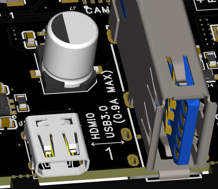
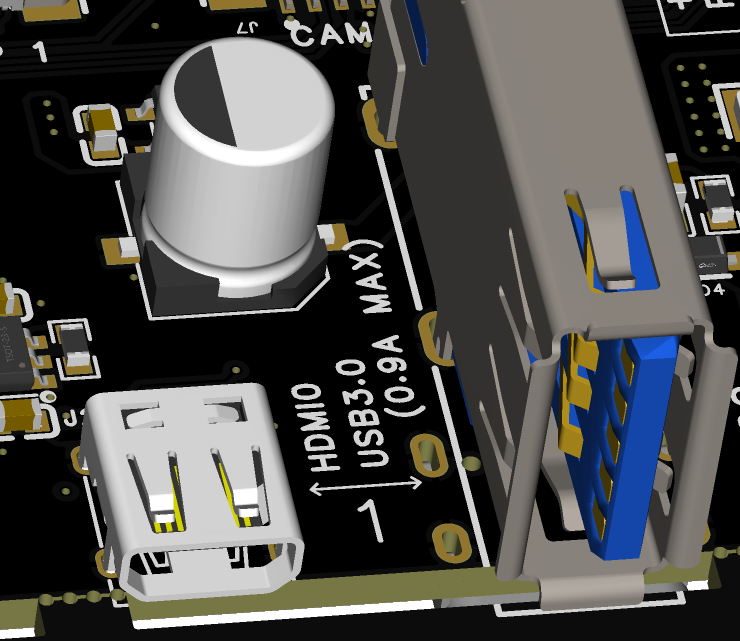
Connected to CM5 USB3.0 Port 0. Max 0.9A to external devices.
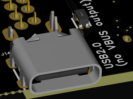
USB 2.0 (Type-C)
D+/D- only, no VBUS. Used with nRPIBOOT for CM5 programming.
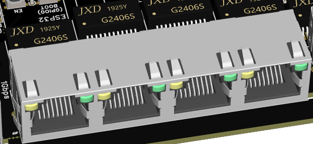
Ethernet (1Gbps)
Native RJ45 from CM5 Gigabit interface. PoE not supported.
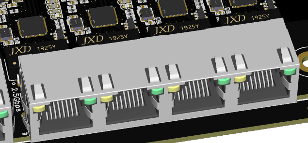
Ethernet (2.5Gbps)
Extended from CM5 USB3.0 Port 1. Supports 10/100/1000/2500Mbps.
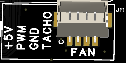
Fan Interface
Same dimensions and signal definitions as the official CM5 IO board. Compatible with Active Cooler JST cable (mounting holes differ).
RTC Battery
Same interface as official CM5 IO board.

MIPI Interface
22-pin 0.5-pitch FPC, same as official CM5 IO board.

Jumper Headers
IO voltage defaults to +3.3V. Brings out GPIO8–GPIO11 for expansion. PMIC_ENABLE can be controlled via jumpers or ESP32.
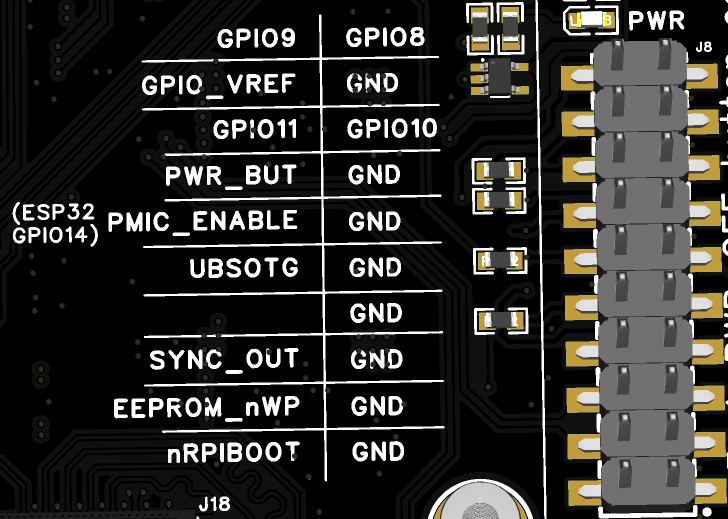
ESP32 Pin Allocation
| Pin | ESP32 | Net Name | Function |
|---|---|---|---|
| 2 | 3V3 | 3V3 | 3.3V Power |
| 3 | EN | EN | HIGH=ON; wired to SW2 |
| 8 | IO32 | XTAL_32K_P | 32.768kHz crystal in |
| 9 | IO33 | XTAL_32K_N | 32.768kHz crystal out |
| 10 | IO25 | CM5_4_PMIC_ENABLE | Channel 4 Enable |
| 11 | IO26 | CM5_3_PMIC_ENABLE | Channel 3 Enable |
| 12 | IO27 | CM5_2_PMIC_ENABLE | Channel 2 Enable |
| 13 | IO14 | CM5_1_PMIC_ENABLE | Channel 1 Enable |
| 16 | IO13 | BMC_I2C_SDA | I2C SDA (INA3221 + J12/J6) |
| 23 | IO15 | BMC_I2C_SCL | I2C SCL (INA3221 + J12/J6) |
| 24 | IO2 | BMC_PSU1 | PSU-1 ENABLE (HIGH=OFF, LOW=ON) |
| 25 | IO0 | BOOT | Boot strap pin |
| 26 | IO4 | BMC_PSU2 | PSU-2 ENABLE |
| 27 | IO16 | BMC_PSU3 | PSU-3 ENABLE |
| 28 | IO17 | BMC_PSU4 | PSU-4 ENABLE |
| 29 | IO5 | #SCS_W5500 | W5500 SPI-CS |
| 30 | IO18 | SCLK_W5500 | W5500 SPI-CLK |
| 31 | IO19 | MISO_W5500 | W5500 MISO |
| 33 | IO21 | #INT_W5500 | W5500 INT |
| 34 | RXD0 | BMC_RXD0 | UART0 RX (J47) |
| 35 | TXD0 | BMC_TXD0 | UART0 TX (J47) |
| 36 | IO22 | #RST_W5500 | W5500 RST |
| 37 | IO23 | MOSI_W5500 | W5500 MOSI |
Buttons
BOOT (SW1): Hold while powering on to enter ESP32 programming mode (via UART J47). In default firmware, holding for >1s then releasing sequentially disables CM5 PMIC_ENABLE signals and 5V DC/DC channels (~0.5s intervals).
EN (SW2): Resets all CM5_PMIC_ENABLE and DC/DC ENABLE signals.
I2C Addresses
| Item | Address / Pins | Description |
|---|---|---|
| J12 | 4-pin 2.54mm (GND, 3V3, SDA, SCL) | OLED module header |
| J16 | 4-pin 2.54mm (GND, 3V3, SDA, SCL) | Additional I2C devices |
| INA3221 #1 | 0x40 | DC1, DC2, 5V Ch.1 |
| INA3221 #2 | 0x41 | 5V Ch.2, 5V Ch.3, 5V Ch.4 |
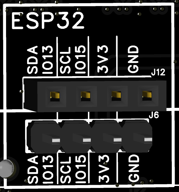
ESP32 Default Firmware
The onboard ESP32 firmware supports:
- Display WiFi mode and IP address on OLED (SSD1306)
- Control power for 4 DC/DC channels and CM5 PMIC_ENABLE signals
- Drive SSD1306 OLED modules
- Sample current on 6 channels (2 DC inputs + 4 × 5V rails)
- Detect W5500 Ethernet connectivity (displays "W55" or "OFF")
The full firmware including web controller is available separately. Source code and schematics will be open-sourced after final firmware testing.
Web Controller
Flash the web-controller firmware to enable remote monitoring and power control via a browser.
Connection Modes
AP Mode (default):
Before connecting to a WiFi network, the board broadcasts:
- SSID:
Super4C - Password:
12345678
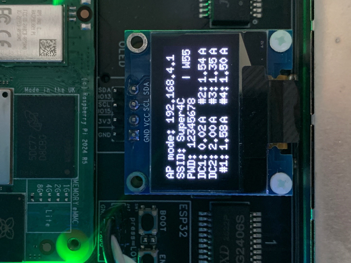
Connect to Super4C WiFi, then open 192.168.4.1 in a browser.
Station Mode:
- Click
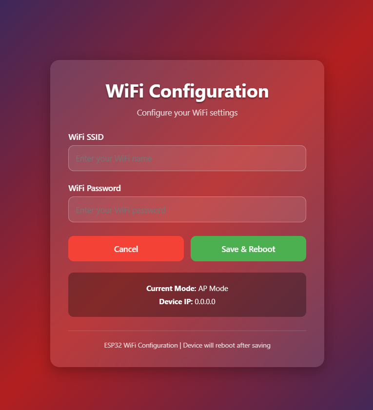
WiFi Setupin the web interface. - Enter your SSID and password.
- Click
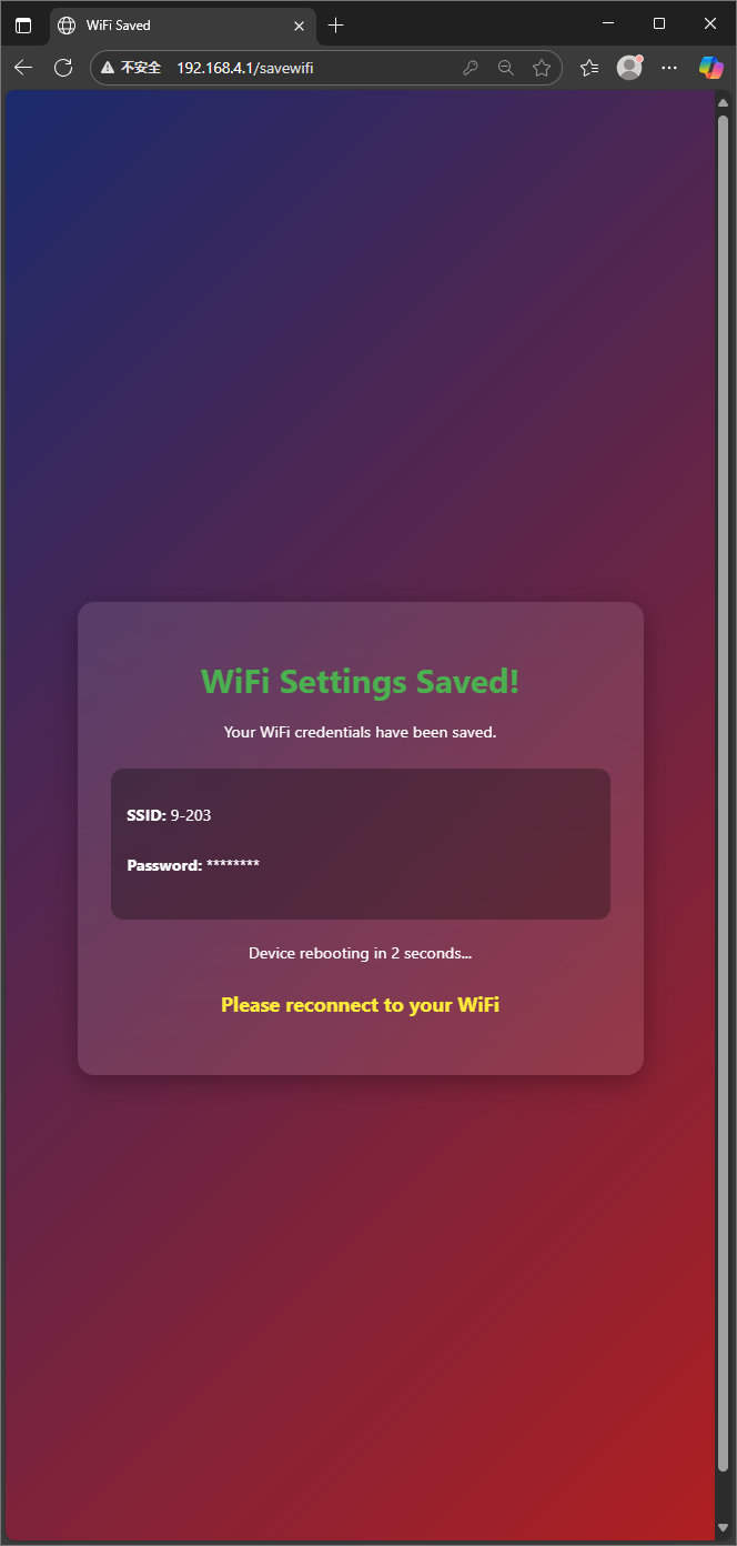
Save & Reboot(takes ~10 seconds). - After reboot, the OLED shows the new IP address.

Reset to AP Mode:
Hold the BOOT button for more than 5 seconds.
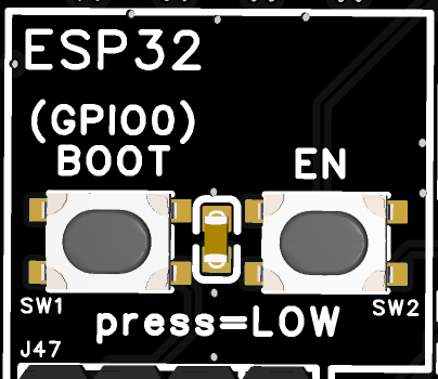
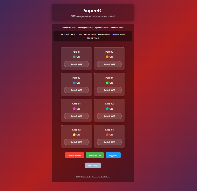
Main Page
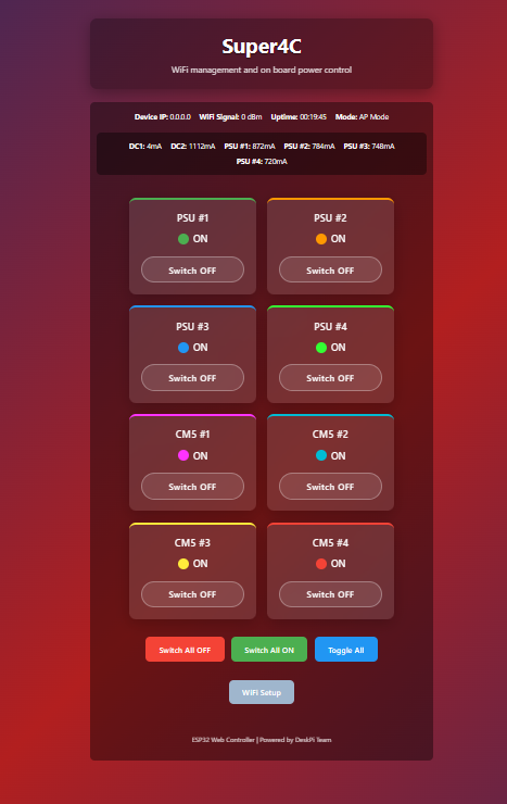
Displays:
- Current mode and IP address
- Signal strength and server uptime
- Real-time current for all 6 monitoring channels
- 8 independent power switches: PSU #1–4 and CM5 #1–4
WiFi Configuration
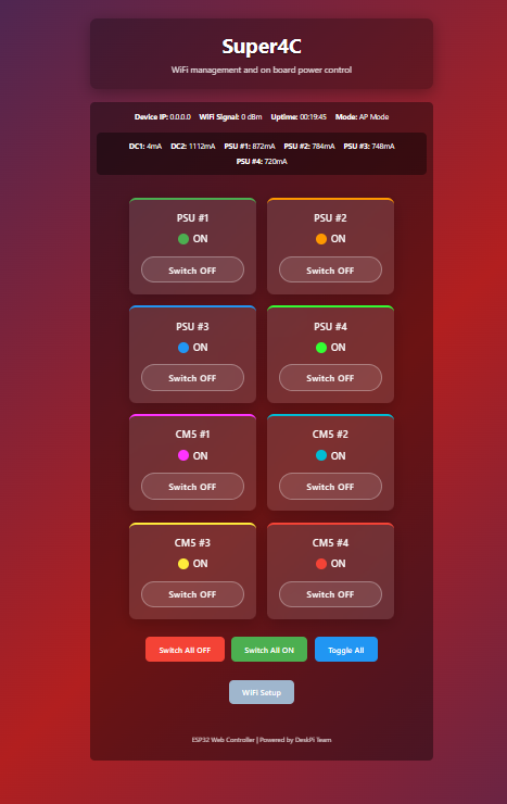
Connect to the Super4C AP, then navigate to 192.168.4.1:
Power Switch Operations
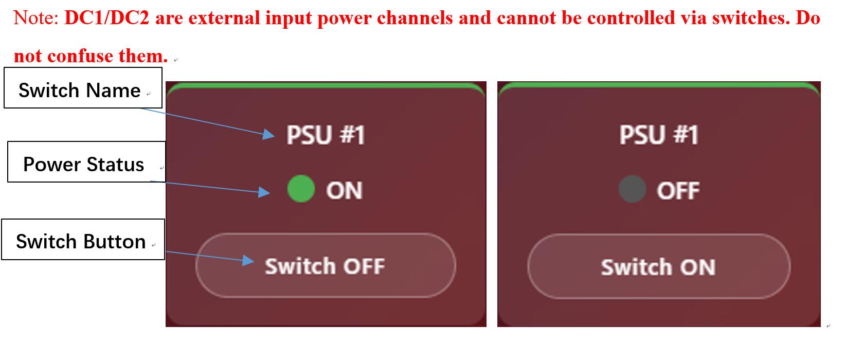
- PSU #1–4: Controls 5V DC/DC per channel — cuts power to CM5, NVMe, SD, USB, 2.5G network in that channel.
- CM5 #1–4: Controls only the CM5 PMIC_ENABLE signal — NVMe, SD, USB, 2.5G remain powered.
- Switch All OFF / ON / Toggle All: Bulk operations — use with caution.
DC1/DC2 are external input channels and cannot be switched. Do not confuse with PSU #1–4.

OLED Display
After attaching an SSD1306 OLED:
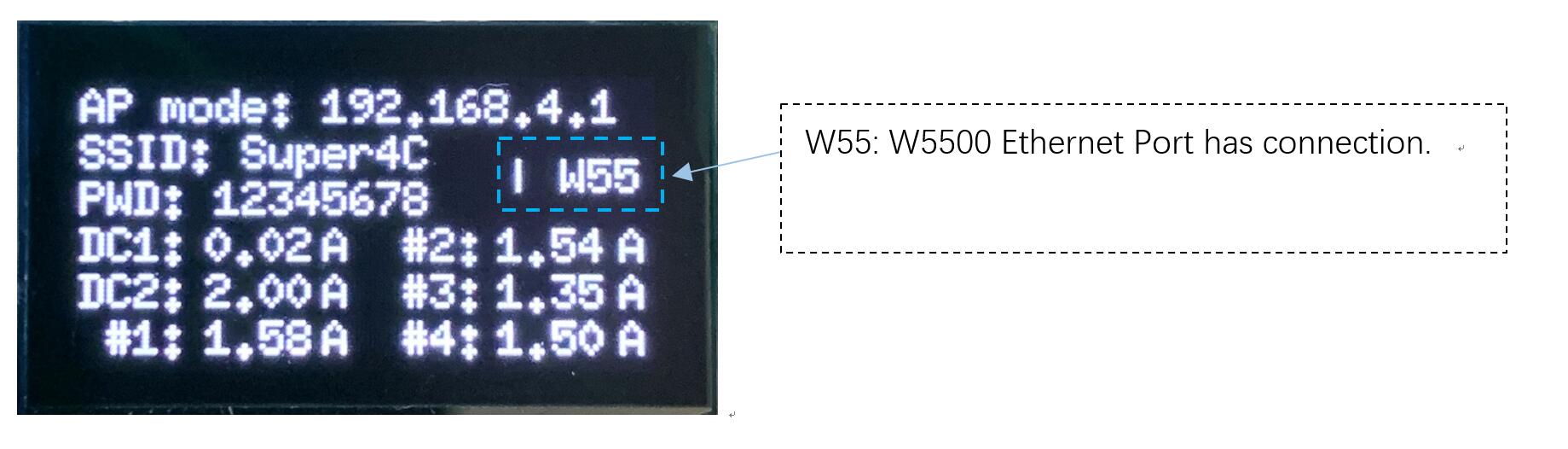
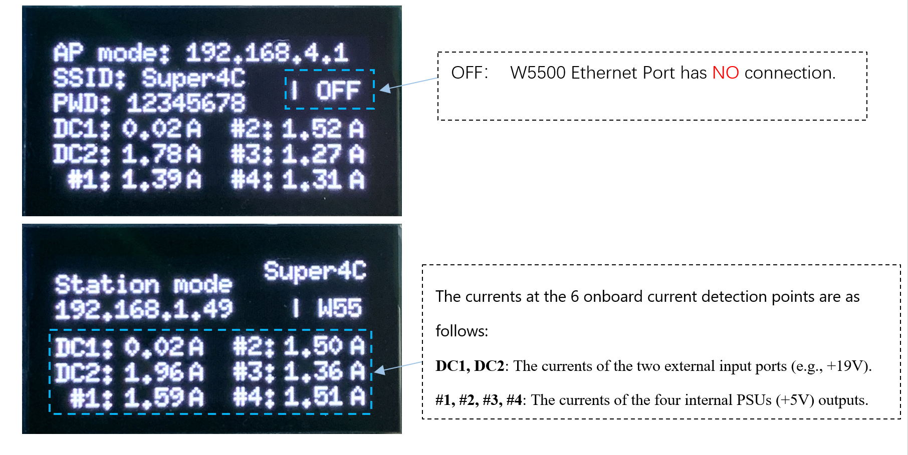
Displays WiFi mode/IP and current readings for all 6 channels (in Amps).
Flash Image to CM5
Set Up the Board
- Connect the CM5 to the Super4C board (flat when seated).
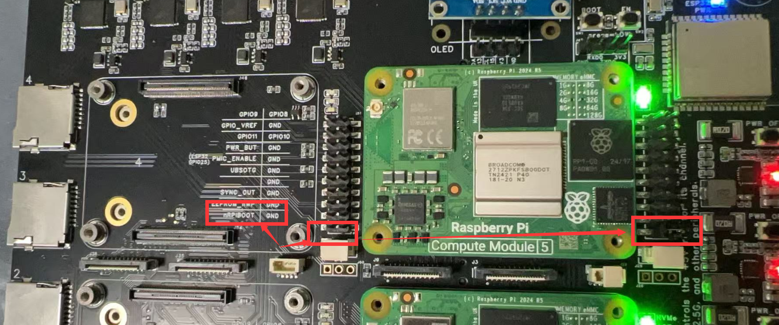
- Fit
nRPI_BOOTjumper to GND pin (J2 — disables eMMC boot).
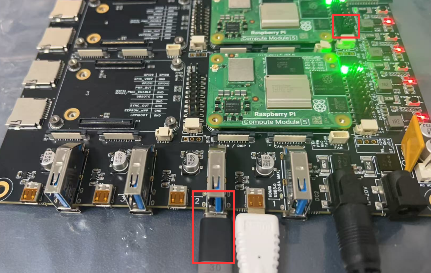
- Connect USB-C cable from slave port J11 to your host.
Linux
sudo apt install rpiboot
# Connect IO board to power, then:
sudo rpiboot
After a few seconds, the CM5 eMMC appears as /dev/sda or /dev/sdb.
macOS
Build rpiboot from source, then:
rpiboot -d mass-storage-gadget64
Click Ignore when macOS says the disk is unreadable. The CM5 now appears as a mass storage device.
Windows 11
- Download rpiboot Windows Installer
- Run installer (do not close any driver windows).
- Reboot.
- Connect IO board to power.
- Launch Raspberry Pi - Mass Storage Gadget - 64-bit from Start menu.
Flash the eMMC
Use Raspberry Pi Imager (recommended), or:
sudo dd if=raw_os_image.img of=/dev/sdX bs=4MiB
After writing, disconnect and reconnect — two partitions appear:
/dev/sdX    <- Device
/dev/sdX1   <- First partition (FAT)
/dev/sdX2   <- Second partition (Linux filesystem)
Example — dumping OS from a Raspberry Pi's MicroSD to CM5 eMMC:

Boot from eMMC
- Disconnect the
nRPI_BOOTjumper from GND. - Disconnect the USB slave cable.
- Power-cycle the board — CM5 boots from the new image.
More Information
End-to-End: 4-Node CM5 Cluster with Ansible
0. Hardware & Network Topology
| Node | Role | IP Address |
|---|---|---|
| Raspberry Pi 5 | Ansible Control Node | 192.168.10.1/24 |
| CM5-01 | Compute Module 5 | 192.168.10.11 |
| CM5-02 | Compute Module 5 | 192.168.10.12 |
| CM5-03 | Compute Module 5 | 192.168.10.13 |
| CM5-04 | Compute Module 5 | 192.168.10.14 |
1. Prepare the Control Node
sudo apt update && sudo apt full-upgrade -y
sudo apt install -y python3-pip sshpass jq
pip3 install --user ansible-core==2.16
echo 'export PATH=$PATH:~/.local/bin' >> ~/.bashrc && source ~/.bashrc

mkdir -p ~/cm5-cluster/{inventory,group_vars,playbooks,roles,report}
cd ~/cm5-cluster
2. Inventory & SSH Setup
Create inventory/hosts.yml:
all:
  children:
    cm5_cluster:
      hosts:
        CM501: {ansible_host: 192.168.10.11}
        CM502: {ansible_host: 192.168.10.12}
        CM503: {ansible_host: 192.168.10.13}
        CM504: {ansible_host: 192.168.10.14}
      vars:
        ansible_user: pi
        ansible_ssh_pass: raspberry
        ansible_ssh_common_args: '-o StrictHostKeyChecking=no'
Create playbooks/init-ssh.yml:
---
- hosts: cm5_cluster
  gather_facts: no
  tasks:
    - name: Push public key
      authorized_key:
        user: pi
        key: "{{ lookup('file', '~/.ssh/id_ed25519.pub') }}"
Run once:
ssh-keygen -t ed25519 -f ~/.ssh/id_ed25519 -N ''
ansible-playbook -i inventory/hosts.yml playbooks/init-ssh.yml
3. Basic System Initialization
playbooks/site.yml:
---
- name: Initialize all CM5 nodes
  hosts: cm5_cluster
  become: yes
  roles:
    - common
roles/common/tasks/main.yml:
---
- name: Expand root filesystem
  shell: raspi-config --expand-rootfs
  notify: reboot

- name: Set unique hostname
  hostname:
    name: "{{ inventory_hostname }}"

- name: Update system
  apt:
    update_cache: yes
    upgrade: dist

- name: Install common packages
  apt:
    name: [python3-venv, python3-dev, build-essential, git, htop, vim]
    state: present

handlers:
  - name: reboot
    reboot:
ansible-playbook -i inventory/hosts.yml playbooks/site.yml
4. Python Venv & Data-Science Packages
playbooks/venv.yml:
---
- name: Deploy Python venv with AI/ML packages
  hosts: cm5_cluster
  become: yes
  vars:
    venv_path: "/home/{{ ansible_user }}/venv"
    python_packages: [pandas, numpy, opencv-python, matplotlib, seaborn, xgboost, pillow, onnxruntime]
  tasks:
    - name: Create virtualenv
      command: python3 -m venv {{ venv_path }}
      args:
        creates: "{{ venv_path }}/bin/activate"
    - name: Upgrade pip
      pip:
        executable: "{{ venv_path }}/bin/pip"
        name: pip
        state: latest
    - name: Install packages
      pip:
        executable: "{{ venv_path }}/bin/pip"
        name: "{{ python_packages }}"
    - name: Auto-activate venv on login
      copy:
        dest: /etc/profile.d/venv.sh
        mode: '0644'
        content: |
          [ -d "{{ venv_path }}" ] && source {{ venv_path }}/bin/activate
ansible-playbook -i inventory/hosts.yml playbooks/venv.yml
5. Useful Playbooks
Batch shutdown / reboot:
ansible-playbook -i inventory/hosts.yml playbooks/shutdown.yml
ansible-playbook -i inventory/hosts.yml playbooks/reboot.yml
Get CPU temperature:
# playbooks/cpu_temp.yml
- name: Retrieve CPU temperature from all CM5 nodes
  hosts: cm5_cluster
  gather_facts: no
  become: no
  tasks:
    - name: Execute vcgencmd measure_temp
      ansible.builtin.command: vcgencmd measure_temp
      register: temp_raw
    - name: Parse temperature
      ansible.builtin.set_fact:
        cpu_temp: "{{ (temp_raw.stdout | regex_replace('temp=', '') | regex_replace(\"'C\\n\", '')) }}"
    - name: Display temperature
      ansible.builtin.debug:
        msg: "Host {{ inventory_hostname }} CPU: {{ cpu_temp }}°C"
    - name: Append to summary file
      ansible.builtin.lineinfile:
        path: "./cpu_temp_summary.txt"
        line: "{{ '%Y-%m-%d %H:%M:%S' | strftime }} - {{ inventory_hostname }} - {{ cpu_temp }}°C"
        create: yes
      delegate_to: localhost
Quick Reference
| Action | Command |
|---|---|
| Check connectivity | ansible cm5_cluster -i inventory/hosts.yml -m ping |
| Ad-hoc shell | ansible cm5_cluster -a "uname -a" |
| View JSON report | cat ~/cm5-cluster/report/*.json | jq -s . |
Enjoy your fully-automated CM5 cluster!
Compatible Hardware & Accessories
Super4C is Mini-ITX compatible and pairs cleanly with the following DeskPi cabinets, blank panels, networking, and cable management accessories.
| Name | Link | Function |
|---|---|---|
| DeskPi RackMate T0 (DP-0047) | 10-inch 4U open-frame rack | Hosts Super4C plus patch panels and cable management |
| DeskPi RackMate T1 (DP-0022) | 10-inch 8U enclosed cabinet | The most common Super4C home for 1× Super4C + switch + 2× mini-PCs |
| DeskPi RackMate T2 (DP-0048) | 10-inch 12U enclosed cabinet | For Super4C plus a taller component stack (NVMe shelves, displays, cooling fan panels) |
| DeskPi ITX Case Kit (DP-0010) | Mini-ITX enclosure with PSU and 3 cooling fans | The standalone (non-RackMate) option for Super4C |
| Raspberry Pi CM5 (any RAM / wireless variant) — see raspberrypi.com | Compute Module 5 | Up to 4 modules per Super4C; CM5 Lite or CM5 with eMMC supported |
| 1U Blank Panel (DP-0032) | 10-inch 1U blank panel | Fill empty rack space next to the cluster in the cabinet |
| 2U Blank Panel (DP-0051) | 10-inch 2U blank panel | Fill empty 2U rack space for clean airflow |
| 1U Venting Blank Panel (DP-0045) | 10-inch 1U vented blank panel | Fill empty 1U slot while keeping passive airflow |
| 12-Port CAT6 Patch Panel (DP-0034) | 10-inch 0.5U/1U 12-port CAT6 panel | Front-facing network interconnects for the CM5 nodes |
| 0.5U Cable Management Panel (DP-0044) | 10-inch 0.5U panel with 3 D-rings | Keep CM5 USB-C power cords and Ethernet patch leads organized |
| Cable Entry Brush Panel (DP-0055) | 10-inch 1U brush panel | Dust-controlled cable pass-through to and from the cluster |
| DC PDU Lite 7-CH (DP-0042) | 10-inch 0.5U 7-channel DC PDU | Optional centralized DC power for fans and other rack accessories |
| Cat6A Ethernet Cable (L-0094) | 0.2 m Cat6A patch cable | Short patch leads between Super4C Ethernet ports and the patch panel |