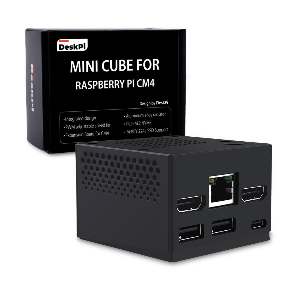
DeskPi Mini Cube
- New Product: ⭐⭐⭐⭐⭐
- Compability: ⭐⭐⭐⭐
- Mobility: ⭐⭐⭐⭐⭐
- Assemble Difficulty: ⭐
Purchase

Description
DeskPi Mini Cube for Raspberry Pi CM4 is a case with a miniature appearance and extremely portable features.
Note: Only supports Raspberry Pi CM4 module
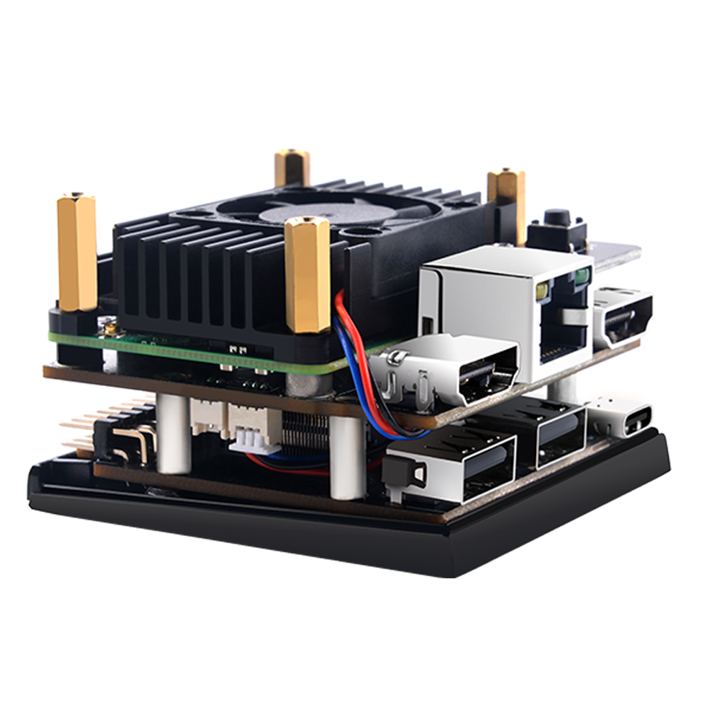
The device provides a mini aluminum alloy radiator and integrates a silent fan that supports PWM speed regulation.
The bottom board provides a wealth of interfaces, supporting dual full-size HDMI interfaces, RJ45 Ethernet interfaces, 2x OTG USB port, and one PCIe interface supports M.2 NVME SSD M-KEY 2242 external storage.
The DIP switch on the back provides the special pins needed to configure the Raspberry Pi CM4 module. (On Compute Module 4 EMMC-DISABLE / nRPIBOOT (GPIO 40) must be fitted to switch the ROM to usbboot mode.)
Otherwise, the SPI EEPROM bootloader image will be loaded instead.
The 40Pin GPIO lead out and reserved RTC clock battery interface.
Features
- Integrated design
- Aluminum alloy radiator with PWM adjustable speed fan
- Power button
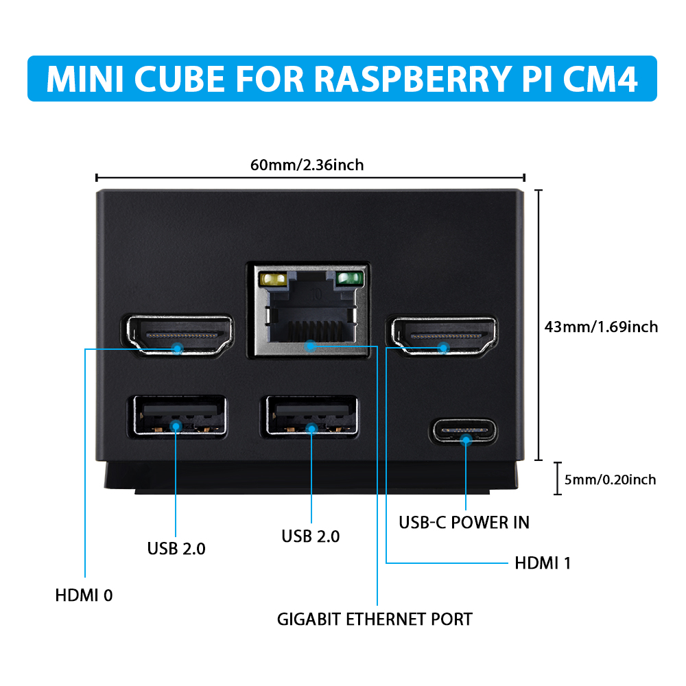
- 2 x Full-size HDMI ports
- 2 x OTG USB2.0 port
- 1 x PCIe M.2 NVME M-KEY 2242 SSD slot
- 1 x 40 Pin GPIO lead out
- 1 x DIP switch for mode change (CM4 function change)
- 1 x Onboard PCF85063 I2C RTC module
- 5V USB-C Port Power IN
Gallery
-
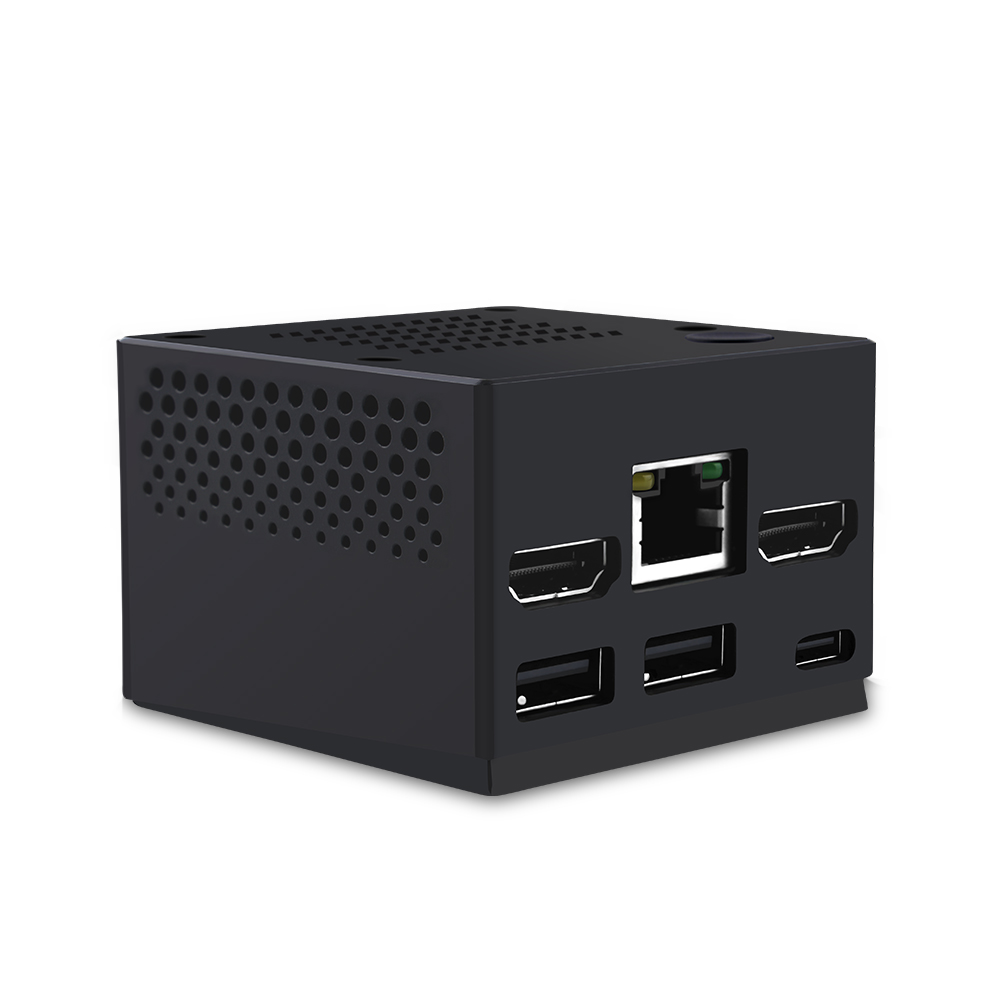
Product Outlook
-
Backside of Mini Cube
-
Ports Definitions
-
Inside of Mini Cube
-
Dimension
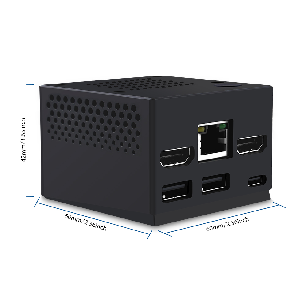
-
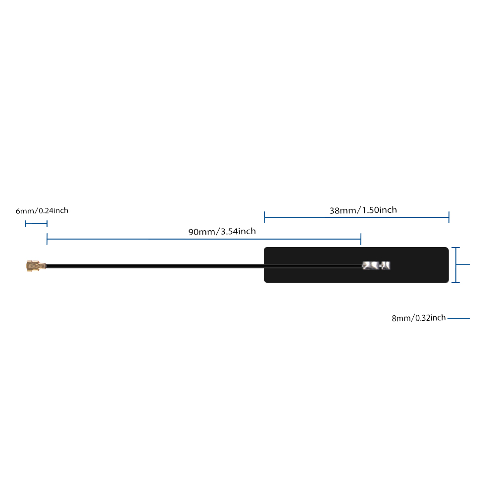
IPX antenna specifications
- Centre Frequency: 2400-2500MHz & 4900-5900MHz
- Connector: IPEX1
- Lead Length:
- Antenna Element Length: mm (+/- 1mm)
- Antenna Element Cable: 1.13 Coaxial cable, with plastic coating.
- Impedance: 5Ohm.
- Gain: About 3 dBi.
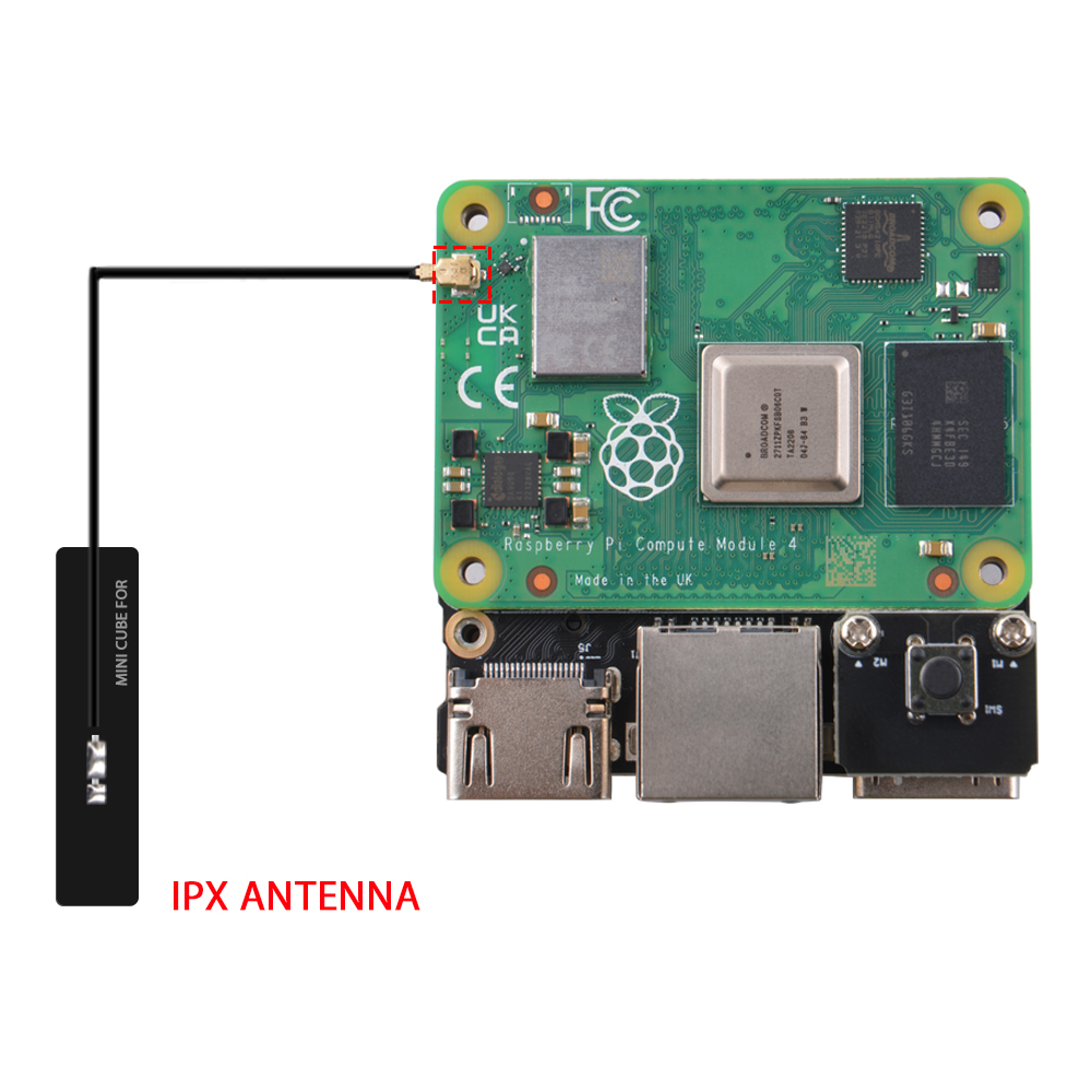
Install IPEX Antenna
Add the antenna as following figure, and then remove the protection film on back of the antenna, and then paste it inside the case.
RTC Battery Information
ear RTC Battery dose not include in the package, additional purchase required!
* Fit for: laptop CMOS Battery, Recommended CR1220 3V with ZH1.25 Connector.
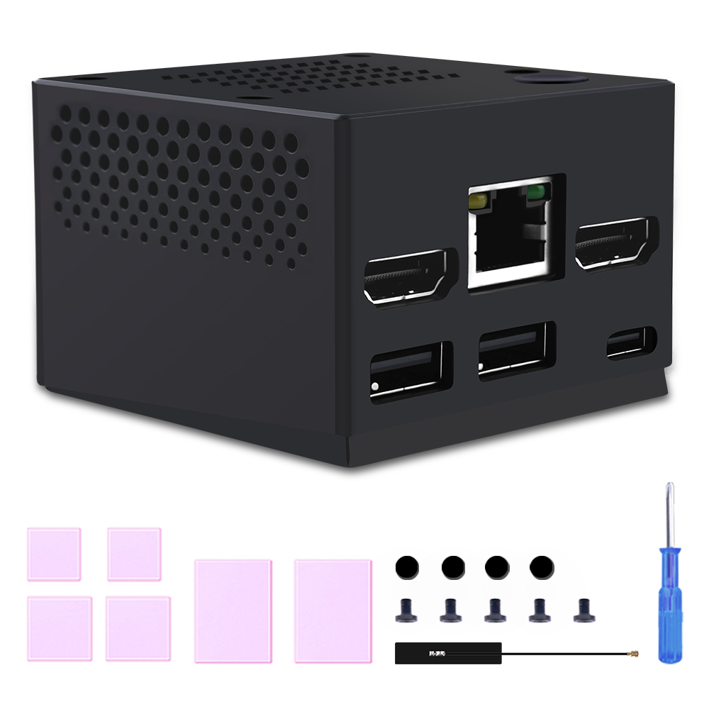
Package Includes
- 1 x DeskPi Mini Cube for Raspberry Pi computer module 4
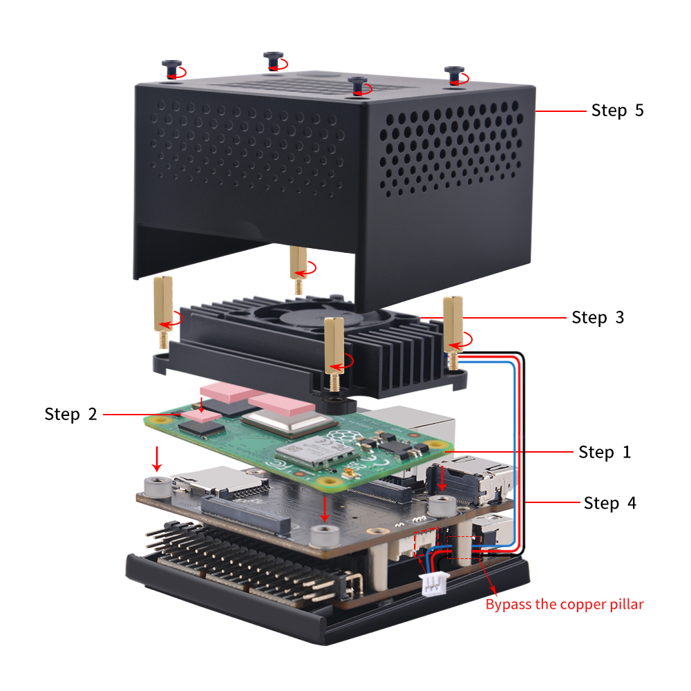
How to assemble it
- Step 1. Unloose four screws on top of mini cube.
- Step 2. Remove copper pillar and paste thermal pad on top of Raspberry Pi CM4 module.
NOTE:Please peel off the protection film on both side of the thermal pad.
and press the Raspberry Pi CM4 module according to following figure, please be ware of the direction and angle when press the Raspberry Pi CM4 module.
- Step 3. Fix aluminum heat sink to Raspberry Pi CM4 module with copper pillars.
Please refer to following figure to assemble it.
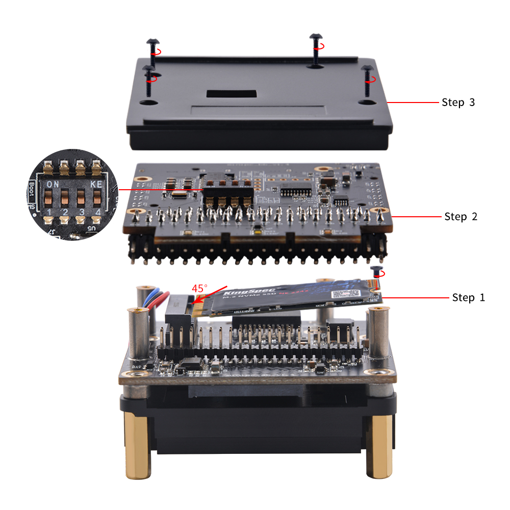
[Optional] Install M.2 NVME SSD M-KEY 2242/2240.
-
Remove the screws on bottom of mini cube and remove the PCB which is connected to mainboard on 40Pin GPIO.
-
Insert SSD drive into the slot in 45-degree angle and fix it with screw.
-
Cover it back to 40Pin GPIO and make sure it connect properly.
-
Fix the bottom case with screws.
Functionality of power button:
- Short Press:
Power on - Long Press:
Power off (Cutoff power)
Please
NOTEthat if you have not shutdown the system, do not use long press to halt system, it will damage your system, it may cause kernel panic or lost file which are not saved yet.
- Correct Operation: Shutdown system in terminal or desktop, and then long press the button to cut off power.
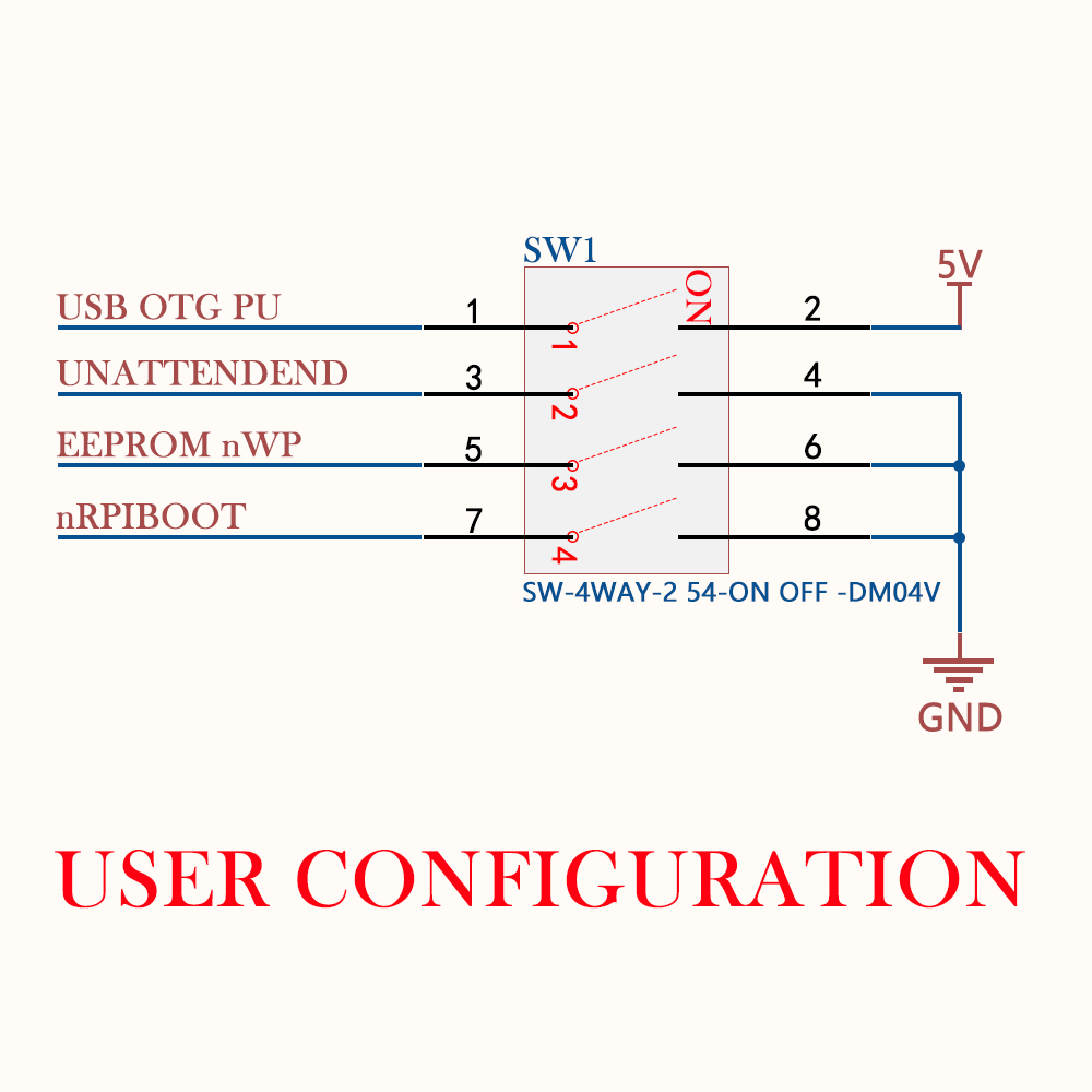
DIP Switch Functionality
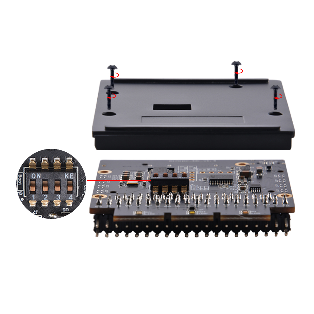
DIP Switch Pinout
- 1 - USB OTG Pull UP
- 2 - UNATTENDEND
- 3 - EEPROM_nWP (EEPROM write protection)
- 4.- nRPIBOOT (disable or enable eMMC Boot)
If you are using Raspberry Pi CM4 with EMMC onboard. please refer to this URL:
How to flash the Compute Module in section “Flashing the Compute Module eMMC”
Hardware write-protection must be enabled via software and then locked by pulling the EEPROM_nWP pin low.
How to enable USB2.0 ports besides the USB-C port?
Assume that you are using Raspberry Pi OS (64bit/32bit).
- The latest official image which you can download from:
www.raspberrypi.com/softwarewill automatically addingotg_mode=1in /boot/firmware/config.txt file, so you don't need to modify any parameter in /boot/firmware/config.txt file.
How to update eeprom on CM4 by using mini cube?
- This is the USB device boot code which supports the Raspberry Pi 1A, 3A+, Computer Module, Computer Module 3,3+,4S and 4, Raspberry Pi Zero and Zero 2W. N.B. In regards to this document CM4 and CM4S have identical software support. The default behaviour when run with no arguments is to boot the Raspberry Pi with special firmware so that it emulates USB Mass Storage Device (MSD). The host OS will treat this as a normal USB mass storage device allowing the file system to be accessed. If the storage has not been formatted yet (default for Compute Module) then the Raspberry Pi Imager App can be used to install a new operating system.
Since RPIBOOT is a generic firmware loading interface, it is possible to load other versions of the firmware by passing the -d flag to specify the directory where the firmware should be loaded from. E.g. The firmware in the msd can be replaced with newer/older versions.
From Raspberry Pi5 onwards the MSD firmware has been replaced with a Linux initramfs providing a mass-storage-gadget.
For more information run rpiboot -h.
Building
- Linux / Cygwin / WSL
Clone this repository on your Pi or other Linux machine. Make sure that the system date is set correctly, otherwise Git may produce an error.
This git repository uses symlinks.
For Windows builds clone the repository under Cygwin
sudo apt install git libusb-1.0-0-dev pkg-config build-essential
git clone --depth=1 https://github.com/raspberrypi/usbboot
cd usbboot
make
sudo ./rpiboot
sudo isn't required if you have write permissions for the /dev/bus/usb device.
macOS
From a macOS machine, you can also run usbboot, just follow the same steps:
- Clone the usbboot repository
- Install libusb (brew install libusb)
- Install pkg-config (brew install pkg-config)
- (Optional) Export the PKG_CONFIG_PATH so that it includes the directory enclosing libusb-1.0.pc
- Build using make
- Run the binary
git clone --depth=1 https://github.com/raspberrypi/usbboot
cd usbboot
brew install libusb
brew install pkg-config
make
sudo ./rpiboot
If the build fails on an ARM-based Mac with a linker error such as ld: warning: ignoring file /usr/local/Cellar/libusb/1.0.26/lib/libusb-1.0.dylib, building for macOS-arm64 but attempting to link with file built for macOS-x86_64 then you may need to build and install libusb-1.0 yourself:
$ wget https://github.com/libusb/libusb/releases/download/v1.0.26/libusb-1.0.26.tar.bz2
$ tar -xf libusb-1.0.26.tar.bz2
$ cd libusb-1.0.26
$ ./configure
$ make
$ make check
$ sudo make install
Running
-
Compute Module 3 Fit the EMMC-DISABLE jumper on the Compute Module IO board before powering on the board or connecting the USB cable.
-
Compute Module 4 On Compute Module 4 EMMC-DISABLE / nRPIBOOT (GPIO 40) must be fitted to switch the ROM to usbboot mode. Otherwise, the SPI EEPROM bootloader image will be loaded instead.
Connect the USB-C cable (from the RPIBOOT host to the MiniCube)
Compute Module 4 Update the SPI EEPROM bootloader.
To update the SPI EEPROM bootloader on a Compute Module 4.
- Modify the EEPROM configuration as desired
- Optionally, replace pieeprom.original.bin with a custom version. The default version here is the latest stable release recommended for use on Compute Module 4.
N.B The bootcode4.bin file in this directory is actually the recovery.bin
file used on Raspberry Pi 4 bootloader update cards.
Booting Linux
The RPIBOOT protocol provides a virtual file system to the Raspberry Pi bootloader and GPU firmware. It's therefore possible to
boot Linux. To do this, you will need to copy all of the files from a Raspberry Pi boot partition plus create your own
initramfs.
On Raspberry Pi 4 / CM4 the recommended approach is to use a boot.img which is a FAT disk image containing
the minimal set of files required from the boot partition.
Troubleshooting
This section describes how to diagnose common rpiboot failures for Compute Modules. Whilst rpiboot is tested on every Compute Module during manufacture the system relies on multiple hardware and software elements.
The aim of this guide is to make it easier to identify which component is failing.
Hardware
- Inspect the Compute Module pins and connector for signs of damage and verify that the socket is free from debris.
- Check that the Compute Module is fully inserted.
- Check that
nRPIBOOT/ EMMC disable is pulled low BEFORE powering on the device. - On BCM2711, if the USB cable is disconected and the nRPIBOOT jumper is fitted then the green LED should be OFF. If the LED is on then the ROM is detecting that the GPIO for nRPIBOOT is high.
- Remove any hubs between the Compute Module and the host.
- Disconnect all other peripherals from the IO board.
- Verify that the red power LED switches on when the IO board is powered.
- Use another computer to verify that the USB cable for
rpibootcan reliably transfer data. For example, connect it to a Raspberry Pi keyboard with other devices connected to the keyboard USB hub.
Hardware - CM4
- The CM4 EEPROM supports MMC, USB-MSD, USB 2.0, Network and NVMe boot by default. Try booting to Linux from an alternate boot mode (e.g. network) to verify the
nRPIBOOTGPIO can be pulled low and that the USB 2.0 interface is working. - If
rpibootis running but the mass storage device does not appear then try running therpiboot -d mass-storage-gadgetbecause this uses Linux instead of a custom VPU firmware to implement the mass-storage gadget. This also provides a login console on UART and HDMI.
Software
The recommended host setup is Raspberry Pi with Raspberry Pi OS. Alternatively, most Linux X86 builds are also suitable. Windows adds some extra complexity for the USB drivers so we recommend debugging on Linux first.
- Update to the latest software release using
apt update rpibootor download and rebuild this repository from Github. - Run
rpiboot -v | tee logto capture verbose log output. N.B. This can be very verbose on some systems.
bootcode.bin
Be careful not to overwrite bootcode.bin or bootcode4.bin with the executable from a different subdirectory. The rpiboot process simply looks for a file called bootcode.bin (or bootcode4.bin on BCM2711). However, the file in recovery/secure-boot-recovery directories is actually the recovery.bin EEPROM flashing tool.
How to enable fan automatically?
** Assume that your operating system is Raspberry Pi OS (32bit/64bit) **
Official Fan setting
- Open a terminal and typing following command:
Navigate to Performance Options -> P4 Fan -> Yes -> 14 -> 60 -> yes -> finish -> reboot Raspberry Pi.
The fan is support PWM signal control via GPIO14 which is physical pin 12(TXD), it will spinning when the CPU temperature is above 60 degree.
and also you can write your code to control the fan via GPIO14, sending PWM signal will trigger the fan spinning.
Control Fan manually
Demo code
- Here is a demo code for controlling fan speed by using python script.
 #!/usr/bin/python3

import RPi.GPIO as GPIO
import time
import subprocess

GPIO.setmode(GPIO.BCM)
GPIO.setup(14, GPIO.OUT)
pwm = GPIO.PWM(14,100)

print("\nPress Ctrl+C to quit \n")
dc = 0
pwm.start(dc)

try:
    while True:
        temp = subprocess.getoutput("vcgencmd measure_temp|sed 's/[^0-9.]//g'")
        if round(float(temp)) >= 45:
            dc = 100
            pwm.ChangeDutyCycle(dc)
            print("CPU Temp:",float(temp)," Fan duty cycle:",dc)
            time.sleep(180.0)
        if round(float(temp)) >= 40:
            dc = 85
            pwm.ChangeDutyCycle(dc)
            print("CPU Temp:",float(temp)," Fan duty cycle:",dc)
            time.sleep(120.0)
        else:
            dc = 70
            pwm.ChangeDutyCycle(dc)
            print("CPU Temp:",float(temp)," Fan duty cycle:",dc)
            time.sleep(60.00)

except KeyboardInterrupt:
    pwm.stop()
    GPIO.cleanup()
    print("Ctrl + C pressed -- Ending program")
Then execute it:
How to enable onboard RTC module?
Save it and please reboot your Raspberry Pi.
NOTE:
RTC battery sock type: ZH1.25
The battery dose not include in the package, additional purchase required!! * Step 1. Modify /boot/config.txt file and adding following parameter:
- Step 2. Check if RTC module has been recognized by Raspberry Pi.
Execute following command in a terminal:
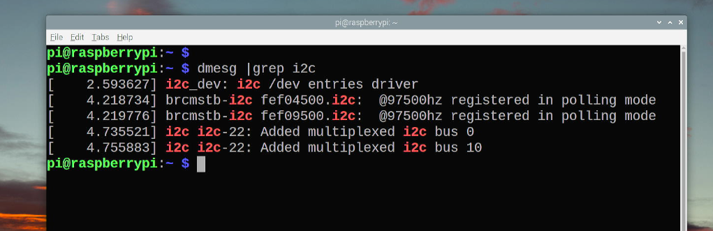
NOTE: if command not found, please install
i2c-tools: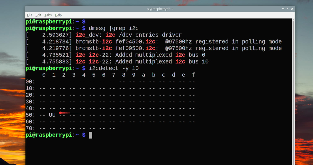
-
Step 3. Probe the module
rtc-pcf85063and check the kernel module status.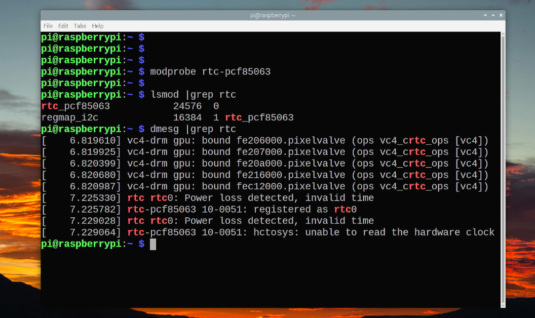
-
Step 4. Setting system date and sychronized system time to Hardware clock time.
** Check RTC time in command line.
** Setting system time Syntax
For example: It means setting system time to 2023.05.31 18:06:23.** Sychronizing system time to HW clock time.
** Check RTC time and system timeFAQ
- Q: Dose it support NVMe SSD booting?
A: It has been tested, yes, it supports, but you may need to upgrade eeprom by using rpi-boot from official github repository.